.webp)
1. FIRST STEPS
Congratulations on your purchase of the ELITE SOLDAmaq 320 welding machine for bands saw.
Read this guide before you start.
The ELITE SOLDAmaq 320 welding machine with "MIG" welding system is suitable for welding and repairing steel saw blades for sawmills from 60 to 320 mm (2,36" up to 12,5")
This manual introduces you to the main functions of the welder in order to avoid risks to your health or that may cause a breakdown or premature wear of the machine.
In case of any doubt, please contact us directly or one of our authorized distributors.
Informative Note: The use described in the manual of this welder may present some variations in use since our machinery is subject to possible constructive modifications, depending on the incorporation of technological advances in our welding equipment.
2. SECURITY
2.1.Safety rules and compliance standards
Carefully observe and apply the following safety rules, non-observance of these rules may cause personal injury or damage to the machine itself.
The installation and maintenance of the machine described in this manual must be carried out only by operators who are familiar with its operation and have sufficient technical knowledge.
The ELITE welding machine SOLDAmaq 320 has been designed for the welding and repairing of steel saw blades, excluding any other type of operation.
DANGER HIGH VOLTAGE
DANGER OF ACCIDENT
DANGER OF HOT SURFACE

DANGER DUE TO SPARK PROJECTION

WEAR PROTECTIVE SHOES

DANGER FROM SHARP TOOLS

USE HEARING PROTECTORS
These warnings do not include all possible risks that improper use of the machine could cause. For this reason, the operator must proceed with prudence and observing the rules.
2.2.Use and storage of the instruction manual
This instruction manual must be read and understood by all personnel who come into contact with the machine.
This manual is for:
- Indicate the correct use of the machine according to the type of work to be carried out.
- Provide the necessary instructions for the transport, adjustment and maintenance of the machine.
- Facilitate the ordering of spare parts and information of risks.
Limits of use of the manual:
The machine is intended for professional use and therefore the experience of the operator is required and of vital importance.
Importance and conservation of the manual:
This manual must be considered part of the machine and must therefore be attached to it until the end of its use.
Additional information and clarifications:
The user, owner or maintenance person can contact the manufacturer to request any additional information on the use of the machine and possible modalities for maintenance and repair intervention.
Expiration of responsibility:
The manufacturer is considered exempt from any liability in the event of:
- Improper use of the machine
- Use of the machine by untrained persons
- Serious failures in scheduled maintenance
- Unauthorized interventions or modifications
- Use of non-original spare parts.
2.3.Declaration of conformity
The company hereby:
ELITE Sharpening Machines, SLU
Joan Oró, 27
ES-08635 Sant Esteve Sesrovires
Declares that the product indicated below, based on its conception and construction, as well as the version put on the market by our company, complies with the mandatory basic health and safety requirements of the CE directive.
This declaration loses its validity in the event of unauthorized modifications to the product.
Product name: ELITE model SOLDAmaq 320
Product type: Welding machine for for bands saw
Serial No.: __
EC Directive Competences:
- EC Machinery Directive (2006/42/EC)
- European directive on electromagnetic compatibility (2014/30/EU)
- The protection purposes of the CE low voltage directive (2006/95/CE) were fulfilled according to annex I, nr. 1.5.1 of the machinery directive 2006/42/EC
The technical documentation was compiled by legal representative of the documentation:
Sergi Valls Gramunt
Joan Oró, 27
ES-08635 Sant Esteve Sesrovires
Date / manufacturer - Signature: __
Signatory data: Sergi Valls Gramunt, manager
2.4 Electrical safety
2.4.1 Connection to the supply circuit
Work on electrical installations ust be done by personnel qualified to do it. By qualified personnel, we mean personnel who are qualified withing the meaning of national legistlation and/or practice and who, because of their technical training, are able to appreciate the dangers of arc welding and electricity.
Before connecting up any arc welding equipment make sure that:
- the main switch is in the "OFF" position;
- the meter, the overload and short circuit protection device, the supply sockets and plugs and the electrical installation are compatible with the maximum power and the supply voltage rating (refer to the welding/cutting equipment manufacturer's plate) and are in conformity with the national standards and regulations in force;
- the connection, single or 3-phase with a protection wire, is protected by a residual differential current sensitive circuit breaker capable of operating with a seepgae current not exceeding if possible 30 mA;
- the protection wire is not disconnected by the electric shock protection device;
- the supply cable is of the "HEAVY DUTY" type;
- the electricity supply circuit is fitted with an emergency stop device, easily recognisable and positioned to be easily and quickly accessible.
- Class A equipment is not intended for use in residential locations where the electrical power is provided by the public low-voltage sypply system. There may be potential difficulties in ensuring electromagnetic compatibility in those locations, due to conducted as well as radiated disturbances. Only Class B equipment complies with electromagnetic compatibility requirements in both industrial and residential environments, including residential locations where the electrical power is provided by the public low voltage supply system.
2.4.2 Welding circuit
Arc welding and cutting requires strict observance of the safety precautions applicable in relation to electricity.
Before any welding/cutting operation, check that:
- no metal part accessible to operators of their assistants can come into direct or indirect contact with a supply circuit phase or neutral wire;
- the elctrode holders, torches and welding cables are properly insulated;
- the operator is insulated from the ground and from the work piece (gloves, safety shoes, dry clothes, leather apron, etc);
- the current return cable is firmly connected as close as possible to the welding area;
- the welding circuit is made up exlusively of wiring conforming with Harmonisation Document HD 22.6 S2: Conductors and cables insulated with cross-linked materials with maximum assigned voltages of 450/750 V -Part 6: Arc welding cables
When welding operations are carried out in environments with a high risk of electric shocks, e.g.:
- in places where the limited freedom of movement obliges the operator to weld in an uncomfortable position (kneeling, sitting or lying down), in physical contact with condutors;
- in areas totally or partially surrounded by conductors, presenting a high risk of involuntary or accidental contact by the operator;
- in wet, damp or hot places where perspiration considerably reduces the resistance of human skin and the insulating properties of accessories.
Extra precautions are needed, and especially
- in welding/cutting equipment marked must be used;
- the operator's personal protection should be upgraded by using insulating floors or mats;
- the power source should be placed out of the reach of the operator during welding/cutting operations;
- all the equipment connected to the circuit and situated near to the operator should be protected by a residual current sensitive breaker able to operate with a seepage current not exceeding 30 mA.
Never touch the electrode wire (or the nozzle) and the work piece at the same time.
2.4.3 Maintenance / Repair
Maintenance and repair of electrical installations must be delegated to personnel qualified to do it. By qualified personnel, we mean personnel who are qualified within the meaning of national legislation and/or practice and who, because of their technical training, are able to appreciate the dangers of arc welding and electricity.
European Directive 2009/104/EC (working equipment) imposes regular inspections to guarantee that the health and safety regulations are respected and that any deterioration is identified and repaired in time. In general, the case of welding/cutting equipment special attention should be paid to:
- The condition of the insulation (e.g:electrode holders, and welding torches and cables);
- Correct lighttening and cleanliness of the electrical connections (e.g.:plugs, connectors, extension leads, part clamps, etc).
Specific recommendations applicable to your welding/cutting equipment can be found in the "Maintenance" chapter in the operating and maintenance manual.
Repairs must only be done by specialists approved by AIR LIQUIDE WELDING who will replace faulty parts with genuine AIR LIQUIDE WELDING parts.
Before any internal inspecion and repair make sure that the unit is disconnected from the electrical installation by a recognised procedure (by "recognised produce" we mean a set of operations intended to separate and keep the unit disconnected form the power supply).
2.5. Safety against smoke, vapours, and noxious and toxis gases
European Directive 98/24/CE (Chemical agents) lays down the ur leur minimum requirements in the field of worker protectoin against risks duits par to their health and safety resulting, or likely to result, from effects e activity produced by chemical agents present in the workplace, or consequent upon any professional activity involving chemical agents. Emissions in the form of gas, or smoke that is unsanitary, annoying or dangerous workers' health, must be trapped on production as close as possible to the emission source and as effectively as possible.
Welding/cutting operations should be done in suitably ventilated steme areas. Smoke sensors should be connected to an extraction system so that any pollytant concentrations do not exceed the maximum values for worker exposure to European Directives 2000/39/EC and 2006/15/EC and the currently applicable national legislation in the national legislation in force, piration AIR LIQUIDE WELDING offers a wide range of extraction systems to suit your requirements.
Special case of chlorinated solvents (used for cleaning and degreasing): Vapour from chlorinated solvents exposed to radiation from an electric arc, even a long way away, can be transformed into toxic gasses. The use of these solvents should be prohibited in areas where electric arcs are present.
Always check that work pieces are dry before carring out welding/cutting operations.
2.6 Safety agains light radiation
Infrared and ultraviolet radiation from the electrical arc cannot be avoided or sufficiently limited during welding/cutting operations. The exposure value limits set by Directive 2006/25/CE are generally exceeded during the welding/cutting. It is essential to respect the requirements for protection of the operator and the persons in the vicinity of the operator described in European Directive 89/656/CEE (personal protection equipment) and its amendments.
The operator must be protected from the effect of radiation on his skin (burns) and eyes (stray flashes), by appropiate personal protection. This means he must wear:
- Suitable clothes (e.g:apron, jacket, trousers, gaiters, gloves, etc.)
- A welding mask fitted with appropiate eye protection filters and conforming with European Standards EN 169 (Personal eye protection -Filters for welding and conncected techniques -Requirements relative to the transmission factor and recommended use) or EN 379 (Personal eye protection -Automatic welding filters).
Persons in the vicinity of the operator, should be protected from direct or reflected radiation by the interposition of suitable curtains, screens or flexible strip curtains and, if necessary, appropriate clothing and a mask with a suitable filter. Suitable warning signs should be installed to warn of the radiation risks operation in accordance with Directive 92/58/CEE (health & safety sign at work).
AIR LIQUIDE WELDING offers a whole range of personal and collective protection equipment to satisfy your needs.
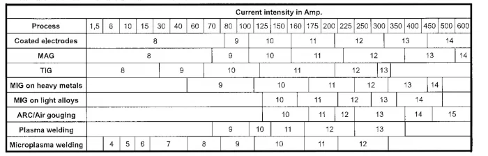
Note: European Standard EN 169 gives the recommended thresholds for various arc welding and connected techniques
2.7 Safety against noise
European Directive 2003/10/CE lays down the minimum health and safety requirements in relationto the exposure of workers as follows:
- When the exposure to noise exceeds 80 dB(A), the employer provides personal ear protection for his workers;
- When the exposure to noise reaches or exceeds 85 dB(A), workers use personal ear protection.
- Noise exposure may not exceed 87 dB(A), taking account of the use of personal ear protectors.
The noise produced by a welding/cuting machine mainly depends on the process, the curent used and the environment. The off-load noise of AIR LIQUIDE WELDING welding/cutting generators is normally less than 70 dB(A). During welding or cutting the noise level (sound pressure level) of these generators can exceed 85 dB(A) at the workstation.
The employer must take appropriate measures in relation to the working conditions. If necessary the employer provides the operator with suitable personal ear protection (ear plugs, safety earmuffs, etc.) and installs appropriate warning signs in the workplace. Conf 92/58/CEE AIR LIQUIDE WELDING offer a wide range of personal protection equipment to suit your needs.
2.8 Fire safety
Welding/cutting processes can cause fires and explosions. Before any Welding/cutting operation, a preliminary risk analysis should be carried out. To reduce fire risks inflammable material should be removed from the weldng area whenever possible.
Whenever possible proceed as follows:
- Cover the inflammable material with incombustible material for example, beams or planks in combustible wood
- Keep the work environment under observation for a sufficient period after the end of the welding/cutting operations;
- Keep "hot points" and their immediate vicinity under observation until their temperature falls to normal;
- Have available fire extinguishing equipment suitable for the equipment used and suitable for use in electrical environments.
National regulations may require a clearance for work procedure prior to the welding/cutting operation.
2.9 Safety when using gas
2.9.1 Risks
Unsatisfactory gas usage conditions expose the user to two main dangers:
- Danger of asphyxiation and intoxications;
- Danger of fire or explosion
These dangers are increased when working in confined spaces.
2.9.2 Gas cylinders
Tehgas supplier's safety instructions must be followed, and in particular:
- Storage and usage areas msut have good ventilation, be sufficiently far from the welding/cutting area and other heat sources and be secure from any technical incident.
- The cylinders should be tied down.
- Shocks should be avoided.
- The temperature should not be excessive.
- The cylinder should contain the gas necessary for the process
- Taps must never be greased and should be operated gently.
2.9.3 Pipes and hoses
The gas supplier's safety instructions must be followed, and in particular:
- Pipes colour coded for the gasses must be used.
- The recommended distribution pressure must be adhered to.
- Fixed pipes and rubber hoses should be checked for leaks regularly. To do this use a suitable sensor, or if this is not available, a paint brush and soapy water. Never use a flame to find a leak.
- Pipes should be protected to minimise damage in the workshop.
2.9.4 Pressure valve
Teh gas supplier's safety instructions must be followed, and in particular:
- The cylinder taps should be bled before connecting the pressure valve.
- The pressure adjusting screw should be unscrewed before connection to the cylinder.
- Check the tightness of the connection union before opening the cylinder tap.
- Open the cylinder tap slowly and by a fraction of a turn.
- Never loosen a union under pressure, close the cylinder tap first.
- The pressure valve should correspond with the gas necessary for the process.
2.9.5 Work in a confined space
A working permit system defining all the safety measure shouldalwasy be des implemented before starting welding/cutting operations in confined spaces such as galleries, pipes, pipe-lines, holds of ships, wells, inspection holes, cellars, tanks, vats, reservoirs, ballast tanks, silos and reactors. Suitable ventilation should be installed paying particular attention to on shortages of oxygen, excesses of oxygen and excesses of combustible gasses.
2.9.6 Action following an accident
In the event of an unignited leak:
- Turn off the gas supply; do not use a flame or any electrical appliance in the leakage area.
In the event of an ignited leak:
- If the tap is accessible, turn off the gas supply and use powder fire extinguishers;
- If it is not possible to stop the leak, let it burn and cool the cylinders and the neighbouring installations.
In the event of asphyxiation:
- The work area should only be entered wearing protective gear; otherwise you could become the second victim.
- Transport the victim into the fresh air and start artificial respiration. Call the emergency services
2.9.7 Gas mixtures containing less than 20% of CO2
If these gasses or mistures replace the oxygen in the air there is a risk of asphyxiation because an atmosphere containing less than 17% of oxygen is dangerous.
2.9.8 Hydrogen and hydrogen based gas mixtures
In the event of a leak, the hydrogen and hydrogen based gas mixtures collect under the ceiling or in cavities. install ventilation in the danger areas and store cylinders in the open air or in a well ventilated place. Reduce the risk of leaks by limiting the number of unions.
Hydrogen and hydrogen based gas mixtures are inflammable. There is a danger of burns or explosion. Air/hydrogen and oxygen/hydrogen mixtures are explosive in the following ranges of proportions: 4 to 74,5% of hydrogen in air and 4 to 94% of hydrogen in oxygen.
2.10 Personel safety
The operator should alwasy wear personal protective equipment designed for welding/cutting work. This protection should be:
- insulating (kept dry) to prevent electric shocks;
- clean (no oil present) to prevent ignition;
- and in good condition (no tears) to prevent burns.
AIR LIQUIDE WELDING offers a wide range of personal protective equipment to satisfy your requirements.
Welding/cutting equipment may be heavy. To avoid work-related musculoskeletal disorders, adopt a good technique when handling the load.
Keep protective equipment on while the welds are cooling as slag and slag components may spit.
2.11 Electromagnetic fields
Any electric current passing through a conductor creates a localised electrical and magnetic field. The welding/cutting current causes an electromagnetic field around the cables and equipment. Exposure to electromagnetic fields may have effects that are currently unknown. It is possible to reduce exposure to electromagnetic fields caused by the welding circuit by taking the following action:
- Join the electrode holder cable or the welding harness and the return current cable together over the longest lenght possible - Fix them together with adhesive tape;
- Never wrap the welding/cutting cable round your body or rest it on your shoulder;
- The operator should not be inside the loop formed by the welding circuit - Place the electrode holder/torch cable and the current return cable on the same side of the operator.
- The operator should not be near the power source during welding/cutting operations
Electromagnetic fields can affect the operation of active implants (pacemakers). Active implant carriers should consult their doctors before doing any welding/cutting work.
Some TIG welding and PLASMA cutting power sources use remote "HF" striking systems that can damage electronic equipment in the vicinity of the welding/cutting operation. Before any welding/cutting operation decide to use a contact striking system, or place all sensitive equipment well away from the area.
3.TECHNICAL DATA
In the following information table, find the list of technical specifications of the welders described in this manual.
| TECHNICAL DATA | SOLDAmaq 320 |
|---|---|
| Bandsaw width | From 60 to 320 mm (2-1/3" to 13,2") |
| Bandsaw thickness | From 0.7 to 2 mm (0.027" to 0.078) |
| Installed power | 9 kW |
| AVAILABLE VERSIONS | ||
|---|---|---|
| Model | Packing Size | Weight |
| SOLDAmaq 320 | 1800 x 1300 x 1500 mm. | 380 Kg. |
4. TRANSPORTATION
The ELITE SOLDAmaq 320 is delivered packed in a wooden box.
During all transport and transfer, the machine must be kept in its original vertical position, any variation in this position may lead to the loss of the guarantee.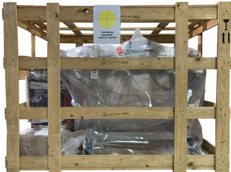
| Model | Packing Size | Gross weight |
|---|---|---|
| SOLDAmaq 320 | 1580 x 1680 x 1960 mm. | 430 Kg. |
4.1.Unpacking and assembly instructions
Take special care when lifting the load: The load may not be centered!
To lift or move the load, use a forklift with blades long enough to support the machine, taking into account the width and depth of the machine for the calculation of the weights to lift.
To unpack, first remove the front panel.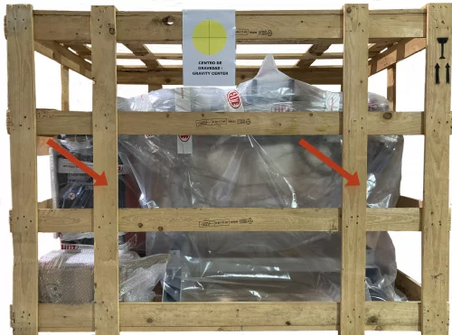
Then remove the wooden fasteners ans screws which fasten the machine to the box.
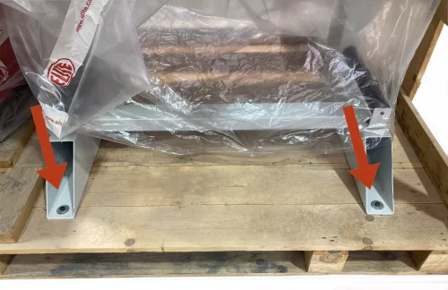
Once the machine is in its final location, you can also remove the protective film and other protections from the components, which secure and prevent the machine from moving.
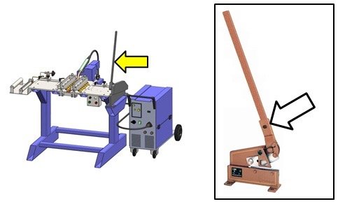
To avoid bulkiness during transport, the cutter lever it is disassembled. Use the bolt shown in the following picture (the cutter is optional) to mount back the lever
5.INSTALLATION
5.1.Machine placement
Before any work, make sure that the machine is well aligned and does not oscillate at any of its ends, in which case it must be shod to prevent movement. For its correct leveling it is necessary to use a leveling tool. This control must be carried out both longitudinally and transversally.
A poor leveling of the machine can cause unwanted vibrations and premature wear of the linear guides.
ATTENTION: The machine must not be used under any circumstances by unqualified or unauthorized personnel.
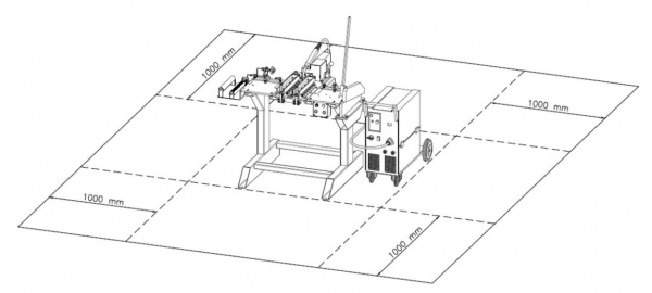
5.2.Free space requirements
The machine must be installed in compliance with the minimum free space requirements as shown below in order to ensure its proper operation, easy maintenance and safety
Lighting:
The area where the machine will be placed must be lighted sufficiently to allow both operation and maintenance works to be performed.
Floor:
To ensure optimal operation of the machine it is required to fix it to the floor using appropriate holes. To ensure maximum safety and eficiency of the operation of the machine an even concrete foor is required.
Position of the operator:
During operation, the operator should be located in front of the machine, slightly to the right (in order to be able to access the control panel) while maintaining a safe distance to prevent the sparks from reaching him during the welding step
5.3.Main components of the machine
Description of parts: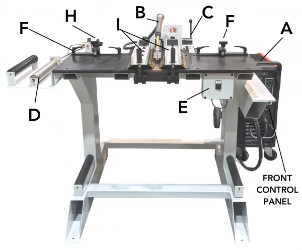
- A: MIG welder
- B: Torch
- C: Automatic actuator torch movement
- D: Burner
- E: START button
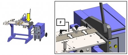
- F: Alignments with clamps
- H: Gas burner knob
- I: Clamp jaws for band saw support
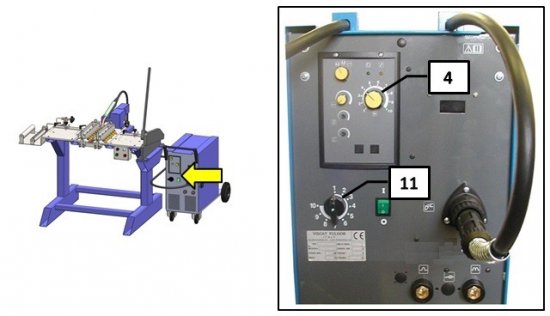
Description of the front control panel: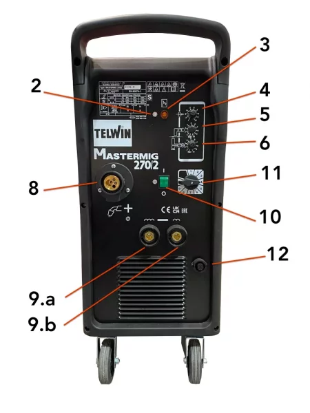
- 2: Machine on led indicator
- 3: Machine overheated led indicator
- 4: Adjustment potentiometer of the wire speed
- 5: Adjustment potentiometer of the welding time (do not touch, the value needs to be set at the minimum)
- 6: Adjustment potentiometer of the acceleration time of the wire draw (do not touch)
- 8: Euro torch coupling
- 9.a: Quick coupling for the ground clamp
- 9.b: Quick coupling for the ground clamp
- 10: Power switch
- 11: Welding voltage adjustment switch
- 12: Start button coupling
5.4.Electrical connection
DANGER HIGH VOLTAGE!
SOLDAmaq welding machines must be strictly connected to the voltage indicated in the machine order and on the machine itself. The connection to a voltage other than that indicated may cause a breakdown in the machine and represents a risk for people who use the machine.
For its connection to the electrical network, the machine requires only two phases and the ground connection.
This installation must be carried out by qualified technical personnel and checked with a voltage meter before turning on the machine.
It is absolutely essential that the cross-section of the connection cable is as required, that the machine has a dedicated socket protected against overloads and that it is as close as possible to the socket.
In case of an inadequate section of the cable, not enough current will reach the machine at the time of welding, causing a defective and extremely fragile weld. This is one of the most important points since a very high number of possible welding problems is due to this problem.
ELITE Sharpening Machines, rejects all responsibility for a wrong connection, which in addition to causing a malfunction of the machine can harm people, animals, material objects.
After installing the wire coil (see section 6.2.2) connect the pin of the torch to the coupling 8 (see components picture in section 5.4), first making sure that the sheath matches the diameter of the wire to be used:
- BLUE colour ø1.5 for wires of ø0.6 -ø0.8 mm
- RED colour ø2.0 for wires of ø1 - ø1.2 mm
Then, connect the plug of the control panel to the coupling 12 (see components picture in section 5.4) and the earthing pin to the coupling 9.b.
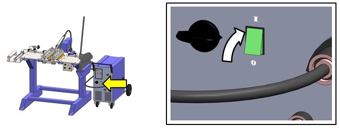
Turn on the welder by pressing the main power switch (Circuit breaker 10, see following figure)
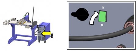
Make sure that the machine is ready to use by checking that the diode on the control panel (diode 2, see components picture in section 5.4) is on.
6.STARTING UP
In this section we show you how to operate the ELITE SOLDAmaq 320 to make it work.
NOTE: The data that appears in the different images are by way of example, each type of tool has its recommended data and an expert operator should know them.
DANGER: never manipulate the buttons on the control panel while performing maintenance on the machine: danger of very serious injury. It is strongly recommended to switch off and disconnect the machine from the mains when working inside it.
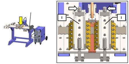
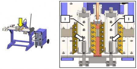
6.1. Adjustment of alignments
First lift the vise I (see components picture in section 5.4) to be able to position the blade on the machine platform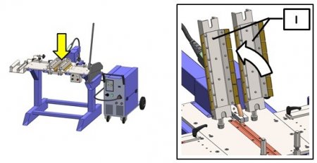
Depending on the height of the blade to be welded, it will be necessary to adjust. In order to do that, release the retainers on the alignments F themselves and slide the alignments into the desired position. If necessary, unscrew the retainers and reposition them in the other openings provided on the plate.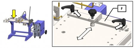
Place the provided array with the machine on the welding platform, so as to align its short side with this throat provided on the copper plate. At this point, support the alignment F agains the long side iof the array. Fix the alignment using the retainers provided. This adjustment may be used to position the other alignment to be made using the blade itself before the cutting stage.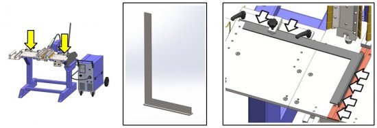
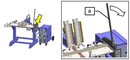
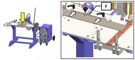
6.2. Band cutting
Exercise caution when handling the band saw and when mounting it on the machine; in order to avoid injury upon contact it is required to wear work gloves. The main operation to be performed prior to welding is to cut the two ends of the band to be welded using the cutter provided. The cut should be at a right angle (90º) relative to the blade profile, so that the two edges to be welded are perfectly adjusted.
To perform the cutting, lift the vise I to be able to position the blade on the machine platform.
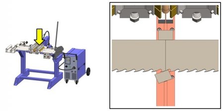
Place the blade on the machine and insert it into the cutter as shown in the following figure (with the teeth facing the operator). Then, adjust the position of the blade following the references F (see components picture in section 5.4). At this point, block the blade using clamps provided on the alignment rails F.
At this point, use lever o fthe cutter so as to perform the cutting. Check that the cutting is being performed correctly, if not, repeat the operation. It will always be preferable to cut the blade on the back side of the tooth (and not at the throat) as this will make easier the arrangement of the weld bead.
ATTENTION: Do not use the cutter to cut the band in the welded area. If you need to delete the portion of the band in the vicinity of the weld, it is necessary to perform an annealing cycle before using the cutter.
6.2. Weldability
6.2.1 Installation of a gas cylinder for welding
- Provide a cylinder containing a mix of 80% ARGON and 20% CO2
- Connect the cylinder to the welder using the chain provided.
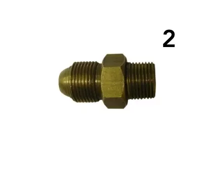
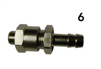
- Connect the reducer (1) to the mixing cylinder (if necessary, insert the provided reduction (2) in between)
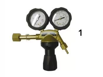
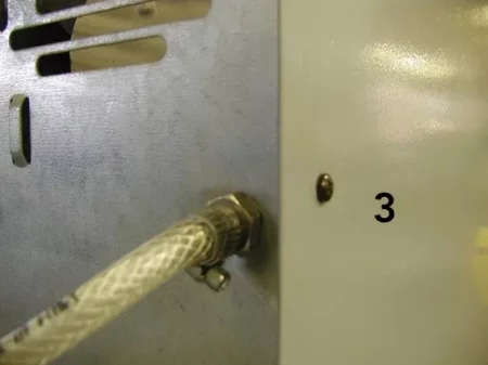
- Connect the hose (3) of the machine to the rubber port of the reducer (1) and fasten it using a metal snap
- Set the output of the presser reducer to the minimum.
- Slowly open the cylinder valve and adjust the output presser to 10L/min.
6.2.2 Installation of a gas cylinder for annealing
Retrieve a PROPANE gas cylinder (GPL)
Position the cylinder in the vicinity of the annealing burner
Connect the reducer (4) configured for PROPANE to the cylinder.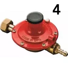
Using the hose (5) and metal snaps provided, connect the reducer to the burner (if necessary replace the rubber port (6)).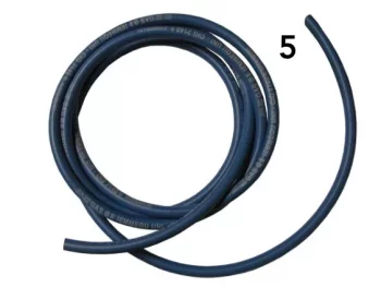
Having permormed the connection, open the cylinder and adjust the presser to the minimum using the reducer 4. The flame intensity can then be adjusted by using the knob H.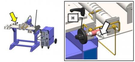
6.2.3. Installation of the wire coil
- Remove cap M and place the wire coil L in the provided sprocket N so that the two subsequently rotate together.
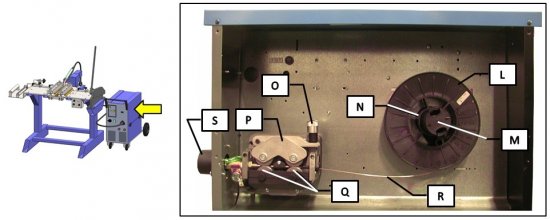
- Adjust the sprocket brake by pressing tis central nut so that the coil can spin relatively smoothly (in some sprockets the adjustment nut is not visible, but it becomes visible after pulling out, outwardly, the locking butt)
- Having released the retainer O, open the top bridge of the draw assembly P.
- Make sure that the rollers Q are suitable for the wire diameter to be used, otherwise replace them.
- Straighten one end portion of the wire R and cut it.

- Remove the gas nozzle guide U from the torch head B and then unscrew and remove also the spout grommet T.
- Insert the wire above the bottom rollers and slip it into the torch coupling S until it comes out of it at about 10 mm.
- Close back the upper bridge of the draw assembly by checking that the wire is positioned in the throat provided and screw back the retainer O.
- Connect the cable of the torch by slipping into the sheath the piece of wire protruding from the coupling. Pay attention to the control plugs by directing them into the seats provided and tighten the connection nut.
- Once the machine is on, while holding the torch, press and keep pressed the START button until the wire protrudes from the torch head. At this point release the START button and reconnect the spout grommet (making sure it matches the type of the wire to be used) and, finally, the gas nozzle guide.
6.2.4. First Start
- Turn on the machine (key 10, see components picture in section 5.4)
- Adjunst the welding voltage (knob 11, see components picture in section 5.4) to a middle position.
- Remove the gas guide U and the spout grommet T from the torch and, pressing the torch button, move the wire until it comes out of from the front portion thereof.
When moving the wire in the torch, use the hand wheel to calibrate the presser that the wire-pressing roller should exert on the drive roller until the welding wire goes smoothly without slipping and without deformations on the rollers. Equip the torch with a spout grommet suitable for the wire used. (DEFAULT Ø0.8). - Screw back the spout grommet T, making sure it matches the wire diameter used.
- Mount again the gas nozzle guide U.
6.3. Technical work data table
| BLADE THICKNESS (mm) | WELDING CURRENT KNOB 11 | WIRE SPEED KNOB 4 |
|---|---|---|
| 0.6 - 0.8 | 1 | 3 - 4 |
| 1 | 2 | 4 - 5 |
| 1.2 | 3 | 4 - 5 |
| 1.3 | 3 - 4 | 4 - 5 |
| 2 | 3 - 4 | 4 - 5 |
NOTE:
Please note once again that the above data is empirical and for guidance only; the thickness, the chemical composition and the technological procedure used in the production of band saw have a very significant impact on the parameters to be set when welding.
We recommend you to conduct various tests on your own bands, based on values suggested here. Amend as necessary where the results were not satisfactory. Set your own tests against the values indicated in the table and, if needed, replace the values indicated herein with those established in the course of conducting your tests.
Remember that nothing can possibly replace one's personal experience.
7.WORK OPERATION
7.1.Welding
Important: it is required to use safety glasses and gloves; when welding beware of sparks.
MIG welder for large blades model SOLDAmaq 320 is a machine with a design based on an innovative concept that allows you to obtain perfect welds at an affordable cost, saving a lot of time and material. The electronic control of the wire speed ensures precise, uniform welds. The machine also allows to repair any cracking that until now have been the essential problem when it comes to large blades. However, please remember that it is not always recommended to try to repair cracking which is sinuous or which exceeds the length of 10-15 mm. It is much more preferable to completely cut and weld the blade.
The blade to be welded must be properly set using the special cutter G (see components picture in section 5.4) provided with the machine (see section 6.2). For proper welding, follow the steps below.
1.Cut two weld beads of the same thickness of the blade to be welded and arrange them at the beginning and at the end of welding; so as to avoid burns at the beginning and at the end of the welds.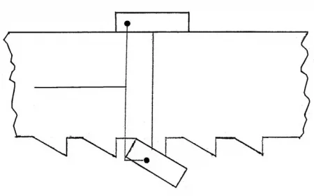
2.Arrange the alignments F (see components picture in section 5.4) based on the height of the blade to be welded. To do this, loosen the retainers on the alignments F themselves. Slide the alignments into the desired position, then lock them using the retainers. If necessary, unscrew the retainers and reposition them in the other holes provided on the plate. (See Chapter 8 for more details). Insert one end of the band to be welded onto the platform of the machine.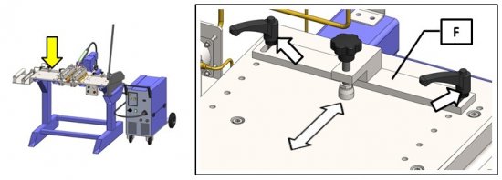
- Place the blade on the machine platform so that it is cenered between the two vise parts I (see components picture in section 5.4). Lock the blade with the side presser of the alignment F
- Repeat the steps 2 and 3 with the other edge of the blade to be welded.
- At this point, close the central vises and lock them by lifting the appropiate levers.
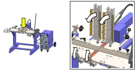
- Having positioned the two edges of the blade, adjust the vises I using the appropriate adjusters.
The adjustment will vary depending on the thickness of the blade. The pressers of the vise I should go along the rear edge of the blade and accordingly be slightly surging forward. - Then, close the vise using the two front levers.
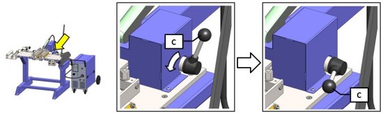
- Unlock the welding torch using the appropriate lever C. Manually position the torch at the weld bead of initial welding (back weld bead)
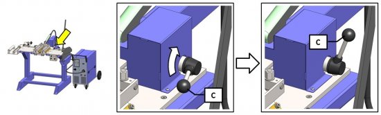
- Lower the lever C, making sure that the engine is in gear (you may need to move the carriage of the torch slightly back and forth in order to facilitate the coupling of the engine)
- Open the gas (5-10 litres/min) (use ARGON 80% and 20% CO2), adjust the welding current (knob 11, see components picture in section 5.4) and wire speed (knob 4, see components picture in section 5.4) as shown in the table attached (see Table in section 6.3).
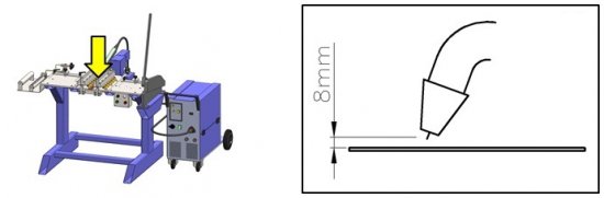
- Ensure that the distance between the torch head and the blade to be welded is about 8mm.
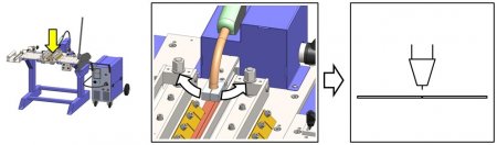
- Rotate slightly the torch support to perfectly centre the nozzle in line with the two edges of the blade to be welded.
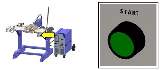
- Watching out for the sparks press the welding START button on the control panel E (see components picture in section 5.4) and keep it pressed. Perform the welding, only finishing it only with the final weld bead. To stop welding, release the button.
- If you notice any welding defects, check the causes and remedies listed in section 7.2.2 (Welding defects)
Beware of sparks! Keep a safe distance from the clamps
Press and keep pressed
7.2.Annealing
Annealing is carried out using the propane gas burner placed on the left side of the machine.
Having removed the two weld beads from the blade, place the welds performed so far in the middle of the burner D (see components picture in section 5.4)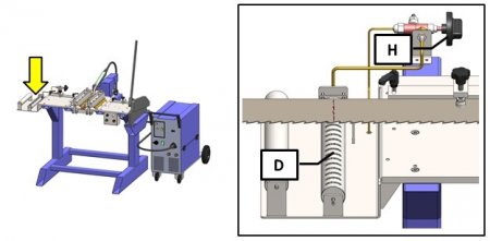
Open the gas from the cylinder, open the gas from the burner valve using the knob H and then turn on the burner using a gas lighter (be very careful when performing this step!). Keep the knob H pressed until the thermocouple reaches the desired temperature. Keep the flame low by adjusting it using the valve H. This allows the deformation of the band to be reduced to minimum.
The machine comes provided with a thermochromic crayon; use it to mark the blade section near to the area to be annealed. When the colour turns white, this means that the exact temperature is reached.
Remove the welding seam from both sides using a standard abrasive means (a small angle sander is recommended).
Your blade is now annealed and ready for use.
7.2.2 Welding defects
The welds obtained with the MIG steps may have several defects, it is therefore important to identify them. These defects do not differ by shape or nature from those that can occur in manual arc welding with coated electrodes. The difference between the two procedures is that the frequency of the defects is not the same, the porosity defects, for example, are more frequent in the case of MIG: while the slag inclusions only occur when welding with coated electrodes. The origin of the defects and the means to avoid them also vary greatly depending on procedure. This table outlays a number of various cases.
Defect: Diference in level
Appearance:
Cause and remedy:
- Poor preparation
- Align the edges and keep them when welding
Defect: Excessive thickness
Appearance:
Cause and remedy:
- Too low voltage at no load.
- Too small welding speed.
- Wrong inclination of the torch.
- Excessive wire diameter.
Defect: Not enough metal
Appearance:![]()
Cause and remedy:
- Too big welding speed
- Too low voltage for the adopted welding speed
Defect: Cords look oxidised
Appearance:
Cause and remedy:
- Weld in the power track when working with long arc
- Adjust the voltage
- Wire is kinked or it goes to far out of the spout grommet.
- Wrong wire speed
Defect: Insufficient penetration
Appearance:
Cause and remedy:
- Irregular or insufficient distance.
- Wrong inclination of the torch
- Spout grommet worn out.
- Wire speed too slow relative to the voltage or the welding speed
Defect: Excessive penetration
Appearance:
Cause and remedy:
- Too big wire speed
- Wrong inclination of the torch
- Spout grommet worn out
- Wire speed too slow relative to the voltage or the welding speed.
Defect: Insufficient melting
Appearance:![]()
Cause and remedy:
- Distance too small
- You need to hew or grind the weld and redo it.
Defect: Power tracks
Appearance:
Cause and remedy:
- Too big welding speed (This defect is easy to spot visually, it must be immediately corrected by the welder).
8.MAINTENANCE
8.1.Preventive maintenance
Disconnect the machine from power before performing any maintenance.
| PERIODIC CHECKS | ||
|---|---|---|
| TYPE OF CHECK | ACTION | WHEN |
| Cleaning the copper plate | Thoroughly clean the surface of the copper plate positioned in the welding area using a coarse cloth, alternatively, you can use compressed air | Before each welding operation |
| Adjusting the plate | Remove the plate and adjust it. After the adjustments, mount the plate again on the machine | When the suface of the plate turns out to be damaged to a considerable extent |
| Verifying plate thickness | Check, using use a calibre, if the upper plane of the plate is not lower than the support platform of the blade | After performing many welds and always after each adjusting |
| Replacing the plate | Remove the worn out plate and replace it with a new one | When the plate is irreparably damaged or when its minimum thickness has been exceeded |
| Smoothness of the carriage | Make sure that the torch gives no jerks when moving during the welding phase | Periodically |
| Cleaning the torch | Spary the torch nozzle with a welding spray and clean the inside of the scaling | Before each welding operation |
| Cleaning the mig welder | Clean the inside of the welder using compressed air to remove the accumulated dust. | Every 5-6 months |
| Cleaning the earthing | Clena the connection between the copper plate and the earthing cable | When necessary |
| Replacing the spout grommet | Replace the spout grommet T (see section 6.2.3) | When necessary |
Use the equipment only in dry environments. The temperature must be between 5 and 40ºC. A relative humidity greater than 90%, as well as a saline environment, would cause premature corrosion of the machine.
8.2. Problems and solutions
Problem: the machine does not turn on
Cause:
- Insufficient mains voltage. Solution: check the mains connection
- Failure of the power button. Solution: check the connection of the power button. Check the functioning of the power button.
- The MIG welder fuse has blown. Solution: replace the fuse
Problem: welding breaks easily
Cause:
- Dirty plate. Solution: clena and / or replace the plate
- Incorrect alignment of the blade during welding: Solution: adjust the parameters (see section 7.1)
- Incorrect welding and /or annealing parameters. Solution: check the parameters (see section 6.3)
Problem: Holes occurring in the weld
Cause:
- The vise does not close properly on the two edges of the blade to be welded. Solution: check that the vise is properly adjusted to the thickness of the blade being welded.
- Welding curent is too high: Solution: check the parameters (see section 6.3)
- The wire speed is too low. Solution: increase wire peed using the knob 4 (see components picture in section 5.4) (see section 6.3)
Problem: Torch undercarriage does not run evenly
Cause:
- There is dirt in the undercarriage. Solution: clean the undercarriage
Problem: The machine does not weld
Cause:
- Failure of the welding start button. Solution: check and / or replace the welding button
- MIG welder failure. Solution: repair the welder
Problem: Uneven welding
Cause:
- No gas. Solution: check that the gas is supplied to the torch
- Gas supply set too low. Solution: increase the gas supply to the torch (see section 6.2)
- Distance of the torch nozzle from the blade is incorrect. Solution: reset the position of the torch relative to the blade (see section 7.1).
Problem: The machine does not anneal
Cause:
- The gas cylinder is empty. Solution: replace the gas cylinder
- The thermocouple has a failure. Solution: replace the thermocouple
Problem: All functions lost
Cause:
- Disrupted power supply (lack of one or more phases). Solution: check and remedy
- Melted fuse. Solution: replace it
Problem: Irregular wire feed
Cause:
- Insufficient spring pressure. Solution: replace it
- Wire guide sheath clogged. Solution: check if screwing the handwheel helps.
- Incorrect throat not matching the wire diameter or excessively worn. Solution: eliminate the hindrance by removing improper coils. If the hindrance persists, replace the wire reel.
Problem: Reduced welding power
Cause:
- The arthing cable is not connected properly. Solution: check the integrity of the cable, check that the earthing clamp is functional and that is applied on the workpiece to be welded free of rust, paint or grease
- The wire is off the transfer switches or loosened. Solution: check and remedy
- Contactor failure. Solution: check the integrity and condition of the contacts and mechanical operation of the contactor
- Rectifier failure: Solution: see if there are no burn marks visible, if so, replace it.
Problem: Porous weld (sponge-like)
Cause:
- No gas. Solution: check if there is a supply of pressurized gas
- Air drafs in the welding area. Solution: use an appropiate screen. If necessary, increase the gas pressure.
- Diffuser opening occluded. Solution: make the opening viable using pressurized air.
- Gas losses due to rupture of hoses. Solution: chcek and replace the defective part.
- The solenoid valve is jammed. Solution: check its operation and the electrical connection.
- Poor quality of the gas or wire. Solution: use an extra dry gas, replace the cylinder or the wire with a different quality one.
Problem: Permanent gas leakage.
Cause:
- Worn or dirty solenoid valve. Solution: dissemble the valve and clean the orifice and the cut-off.
Problem: Pressing the torch button does nothing
Cause:
- Detective circuit breaker, disconnected or broken control cables. Solution: remove the torch spinet and short the poles, if the machine works, check the cables and the torch micro button.
- Melted fuse. Solution: replace with another of the same size
- Detective power switch. Solution: clean with air, check tightening wires, replace.
- Electronic circuit failure. Solution: replace it
9.ACCESSORIES AND CONSUMABLES
10.WARRANTY
All our machines are tested before being shipped. However, there can always be defects that are not observable at first sight.
Our machines are guaranteed against manufacturing or material defects under normal use and maintenance conditions.
The period of this guarantee is 12 months from the date of purchase and consists of the replacement of defective material.
The guarantee will be automatically canceled in the event of a modification outside our company. Or in manifest cases of misuse of the machine.
The guarantee does not include parts subject to normal wear due to use such as skids, lubrication cartridge, abrasives, etc.
11.DOWNLOAD MANUAL
12.FAQ
Question nr1
Answer no. 1