1. FIRST STEPS
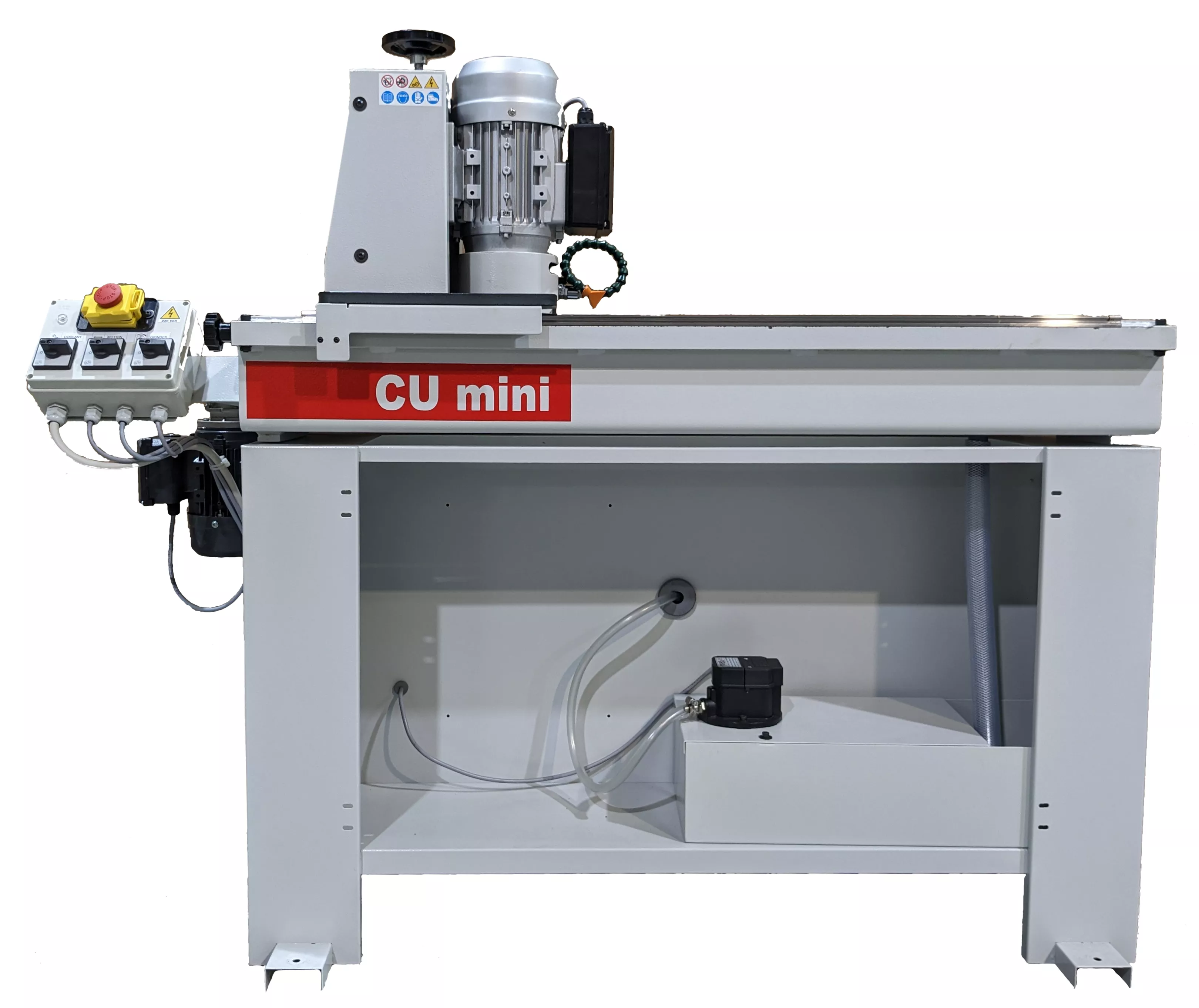
Congratulations on your purchase of the ELITE CU mini 650 knives sharpening machine.
Please read this guide before you begin.
The CU mini 650 sharpening machine is the compact and economical sharpener for planer knives or similar with a capacity of up to 650 mm. of length.
You can view the product catalog at the following link: ELITE model CU mini 650
This manual introduces you to the main functions of the sharpener in order to avoid risks to your health or that may cause breakdown or premature wear of the machine.
If you have any questions, please contact us directly or one of our authorized distributors.
Informative Note: The use described in the manual of this sharpener may present some variations in use since our machinery is subject to possible construction modifications, depending on the incorporation of technological advances in our sharpening equipment.
2. SECURITY
2.1.Security regulations and compliance standards
Observe and carefully apply the following safety rules. Failure to follow these rules may cause personal injury or damage to the machine itself.
Installation and maintenance of the machine described in this manual must be carried out only by operators who are familiar with its operation and have sufficient technical knowledge.
The ELITE CU mini 650 sharpener has been designed for sharpening planer knives or similar, excluding any other type of operation.
DANGER HIGH VOLTAGE

DANGER OF ACCIDENT

DANGER DUE TO SPARK PROJECTION

WEAR PROTECTIVE SHOES

DANGER FROM SHARP TOOLS

USE HEARING PROTECTORS
These warnings do not include all possible risks that could result from improper use of the machine. For this reason, the operator must proceed with caution and respecting the rules.
2.2.Use and conservation of the instruction manual
This instruction manual must be read and understood by all personnel who come into contact with the machine.
This manual is for:
- Indicate the correct use of the machine according to the type of work to be performed.
- Provide the necessary instructions for the transportation, adjustment and maintenance of the machine.
- Facilitate the ordering of spare parts and risk information.
Limits of use of the manual:
The machine is intended for professional use and therefore the operator's experience is necessary and of vital importance.
Importance and conservation of the manual:
This manual must be considered part of the machine and must therefore remain attached to it until the end of its use.
Additional information and clarifications:
The user, owner or maintenance person can contact the manufacturer to request any additional information on the use of the machine and the possible modalities of maintenance and repair intervention.
Expiration of liability:
The manufacturer is considered exempt from any liability in case of:
- Improper use of the machine
- Use of the machine by untrained people
- Serious failures in scheduled maintenance.
- Unauthorized interventions or modifications
- Use of non-original spare parts.
2.3.Declaration of conformity
The company hereby:
ELITE Machines, SLU
C/ Joan Oro, 27
ES- 08635 Sant Esteve Sesrovires, Spain
declares that the product indicated below, due to its conception and construction, as well as the version placed on the market by our company, complies with the basic health and safety requirements of the CE directive.
This declaration loses its validity in the event of unauthorized modifications to the product.
Product name: CU mini 650
Product type: Planer knives sharpening machine.
Serial number: __
Powers of the EC Directive:
- EC Machinery Directive (2006/42/EC)
- European Directive on Electromagnetic Compatibility (2014/30/EU)
- The protection objectives of the EC low voltage directive (2006/95/EC) were met according to Annex I, no. 1.5.1 of the machinery directive 2006/42/EC
The technical documentation was prepared by the Legal Representative of the documentation:
Sergi Valls Gramunt
C/. Joan Oro, 27
ES-08635 Sant Esteve Sesrovires, Spain
Date / manufacturer - Signature: __
Signatory details: Sergi Valls Gramunt, manager
3.TECHNICAL DATA
In the following information table, find the list of technical specifications of the sharpening machine described in this manual.
| TECHNICAL DATA | CU mini 650 |
|---|---|
| Diameter of grinding wheel | ø125 mm. |
| Grinding wheel height | 60mm |
| Grinding wheel mounting hole | 16mm. |
| Grinding wheel motor revolutions | 2,800 RPM |
| Grinding wheel motor power | 0.75kW |
| Carriage motor power | 0.09 kW |
| Pump | 0.06 kW |
| AVAILABLE VERSIONS | ||
|---|---|---|
| Model | Size | Weight |
| CU mini 650 | 1500 x 550 x 1300mm. | 210 kg |
4. TRANSPORTATION
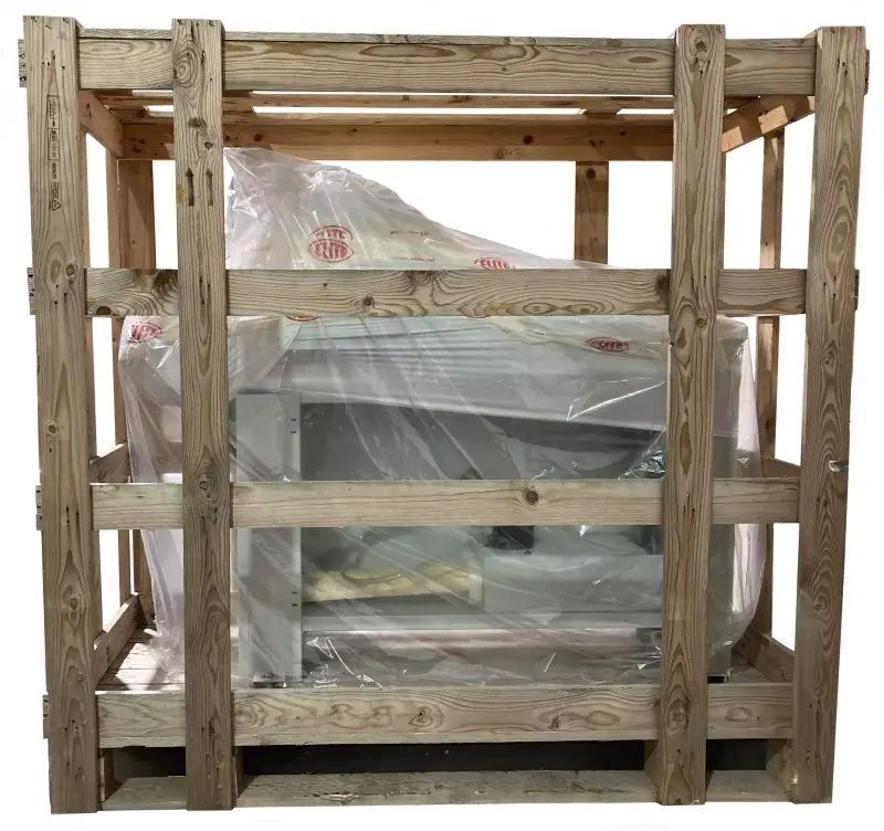
The ELITE CU mini 650 is delivered packed in a wooden box.
During all transportation and transfer, the machine must be kept in its original vertical position; any variation in this position may lead to the loss of the warranty.
| Model | Packaging size | Gross weight |
|---|---|---|
| CU mini 650 | 1710 x 810 x 1620mm. | 240 kg |
4.1.Unpacking and assembly instructions
Be especially careful when lifting the load: the load may not be centered!
To lift or move the load, use a forklift with blades long enough to support the machine, taking into account the width and depth of the machine when calculating the weights to be lifted.
To unpack, first remove the front panel indicated by red arrows in the photo. Then remove the wooden fixings and screws holding the machine to the box, 2 at the front and 2 at the back (indicated by blue arrows in the photo).
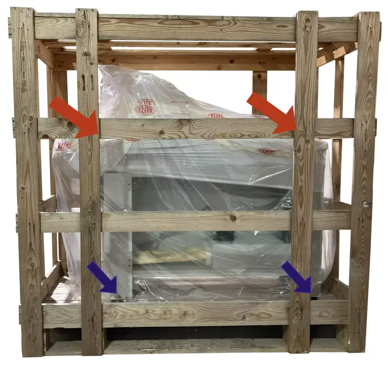
Once the machine is in its final location, you can also remove the protective film and other protections from the components, which secure and prevent the machine from moving.
5.INSTALLATION
5.1.Placement of the machine
Before any work, make sure that the machine is well aligned and does not oscillate at any of its ends, in which case it must be chocked to prevent movement. For correct leveling it is necessary to use a leveling tool. This control must be carried out both longitudinally and transversely.
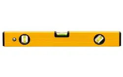
Poor machine leveling can cause unwanted vibrations and premature wear of the linear guides.
ATTENTION: The machine must not be used under any circumstances by unqualified or unauthorized personnel.
5.2.Free space requirements
The machine must be installed respecting the minimum clearance requirements shown below to ensure proper operation, easy maintenance and safety.
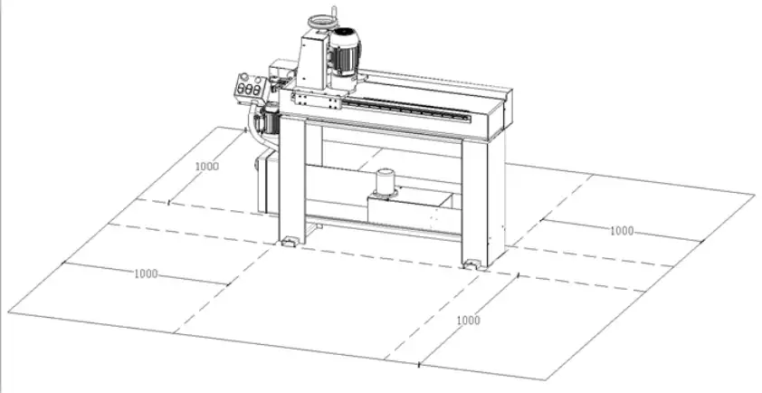
Figure 1
Turning on:
The area where the machine will be located must be sufficiently illuminated to allow both operation and maintenance work to be carried out.
Floor:
To guarantee optimal operation of the machine, it is necessary to fix it to the ground using the appropriate holes. To ensure maximum safety and efficiency in the operation of the machine, a perfectly horizontal concrete floor is required.
Operator position:
During operation, the operator must be positioned in front of the machine, maintaining a safe distance that prevents reaching dangerous areas with the upper and lower extremities.
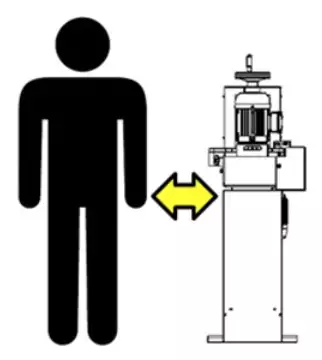
Figure 2
5.3.Main components of the machine
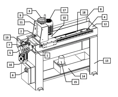
Figure 3.1
Control panel
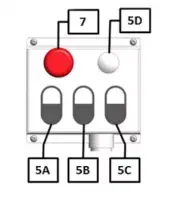
Figure 3.2
Description of parts
- Knob ajusting the grinding wheel automatic lowering
- Clutch to disengage the automatic lowering
- Handwheel for the manual wheel advance of the grinding wheel
- Work plane angle adjustment
- Control panel:
- 5A Coolant pushbutton
- 5B Trolley movement pushbutton
- 5C Grinding wheel rotation pushbutton
- 5D Light indicating power connection
- Disconnect switch
- Emergency pushbutton
- Chain guard
- Trolley guard
- Grinding wheel guard
- Trolley
- Tank
- Base
- Coolant reservoir
- Coolant pump
- Greared motor driving the trolley movement
- Grinding wheel motor
- Work plane
- Plate bearing the machine technical characteristics
5.4.Electrical connection
HIGH VOLTAGE DANGER!
ELITE sharpening machines must be strictly connected to the voltage indicated in the machine order and on the machine itself. Connecting to a voltage other than that indicated may cause damage to the machine and represents a risk to the people who use it.
To connect to the electrical network, the machine must be connected to a three-phase electrical network (400 V or 240 V depending on what is indicated on the identification plate, inserting an electrical panel with the 16 A residual current and magneto-thermal switch, respecting the regulations in force in the country where the machine is installed.
It is recommended that the user's electrical installation complies with CEI 64.8 standards (CENELEC HD 384, IEC 364-4-41)
This installation must be carried out by qualified technical personnel and checked with a voltmeter before turning on the machine.
It is absolutely essential that the section of the connection cable is the required one, that the machine has a specific power outlet and is protected against overloads and short circuits, and that it is as close as possible to the power outlet.
ELITE Sharpening Machines, rejects all responsibility for a poor connection, which in addition to causing the machine to malfunction can damage people, animals, and material objects.
ATTENTION! Check that the direction of rotation of the motors is as indicated by the arrow on them. Carry out the check by turning on the pump and observing its direction of rotation. If the pump rotates in the correct direction, so will the others. Otherwise, the plug phases must be reversed. Run the control again.
6.STARTING UP
In this section we show you how to operate the CU mini 650 sharpener so that it works.
NOTE: The data that appears in the different images is an example, each type of tool has its recommended data and an expert operator should know them.
DANGER: Never manipulate the control panel buttons while servicing the machine: risk of very serious injuries. It is strongly recommended to turn off and disconnect the machine from the mains when working inside it.
6.1. Preliminary controls
DANGER OF ACCIDENT
WEAR PROTECTIVE FOOTWEAR
HAZARD FROM SHARP TOOLS
Before using the machine check there is no material or item in the tank preventing or blocking the trolley movement and the grinding wheel descent. Moreover, check there are no residues from previous working (swarf) on the work plane.
Make sure safety devices are in place and are perfectly intact and operational.
Make sure the machine is perfectly fixed to the ground through the special fixing holes on the machine base.
6.2. Filling with coolant
The knife grinding machine is provided with an automatic cooling system.
Before using the machine after its installation fill it in with the cooling fluid. The coolant tank is located on the machine base (see Figure 6).
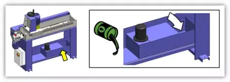
Figure 6
The maximum capacity of the bucket is approximately 11 liters.
Cooling fluid: water with 2% emulsifiable grinding oil.
It is recommended that you occasionally check the coolant level and, if necessary, replenish it.
6.3. Positioning of planer knives
The machine is provided with special blocks allowing the simultaneous sharpening of four planer knives each with a 40°cutting angle and 3-mm thick. To sharpen knives with a different angle and/or thickness you will need special blocks which do not come with the machine.
6.3.1 Adjustment of the sharpening angle

Figure 7
Unloose nut B (see Figure 7) so as to release work plane A (see Figure 7). Unloose screw E (see Figure 7). Rotate the surface until the graduated scale on ring nut C (see Figure 7) indicates the desired angle (in this case 40°) in relation to indicator D (see Figure 7). Now rotate screw E until you have fixed the chosen angle. Tighten nut B in order to fix work plane A.
6.3.2 Adjustment of reference bars (optional accessory)
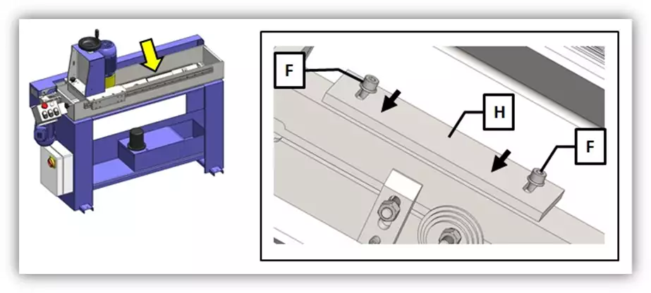
Figure 8
Unloose screws F (see Figure 8) and move the alignment bar H (optional see Figure 8) upwards. Fix alignment bar H using screws F. Repeat this operation on both alignment bars if necessary (as in the case of long knives).
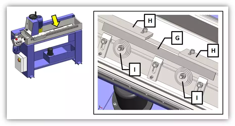
Figure 9
Place a ground bar, G (not included, see Figure 9) having the same height as the knife to be sharpened against alignment bars H (optional see Figure 9). Unloose the screws fastening the step blocks (see Figure 9) and turn the latter until touching ground bar G. Lock blocks I. (If you do not have a ground bar use a comparator to align the blocks).
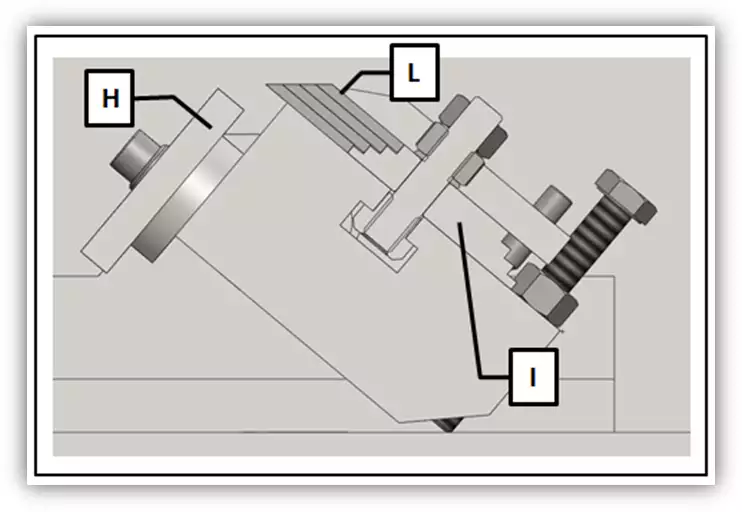
Figure 10
Remove ground bar G (see Figure 10) and insert the 4 knives L (see Figure 10) to be sharpened placing them against their relevant step blocks I (see Figure 10). Unloose alignment bars H (optional see Figure 8 and Figure 10), lower them and fix themback on. If the model you purchased is not provided with alignment bars use a comparator to carry out the alignment (see section 6.3.3).
6.3.3 Knive fastening
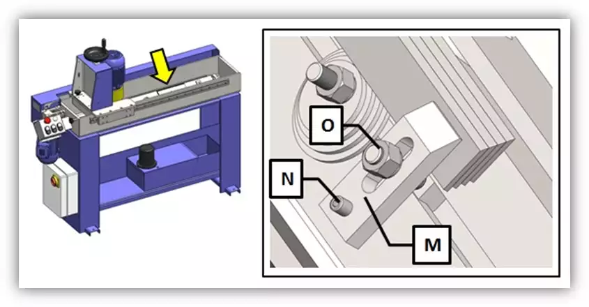
Figure 11
According to the length of the knives to be sharpened use a suitable number of fixing brackets (it is advised that you put a bracket on the knife every 15-cm).
Align fixing brackets M (see Figure 11) along the knife. Adjust the bracket alignment in relation to the knife plane using adjustment screw N (see Figure 11). Now fix brackets M using nuts O (see Figure 11). Before proceeding make sure the fixing brackets do not stick out of the knife sharpening plane.
6.4. Positioning of standard knives
6.4.1 Adjustment of the sharpening angle
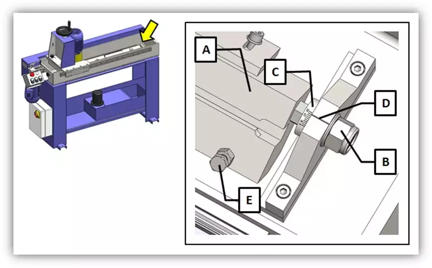
Figure 12
Unloose nut B (see Figure 12) in order to release work plane A (see Figure 12). Unloose screw E too (see Figura 12). Now rotate the plane until the graduated scale on ring nut C (see Figure 12) indicates the desired angle (i.e. the cutting edge angle) in relation to indicator D (see Figure 12). Rotate screw E up to the desired angle. Now tighten nut B to fix the work plane A.
6.4.2 Knife alignment (Optional accessory)
Figure 13
Unloose screw F (see Figure 13) and move alignment bar H (optional see Figure 13) upwards. Now fix alignment bar H using screws F. Repeat this operation on both alignment bars if necessary (as in the case of long knives).
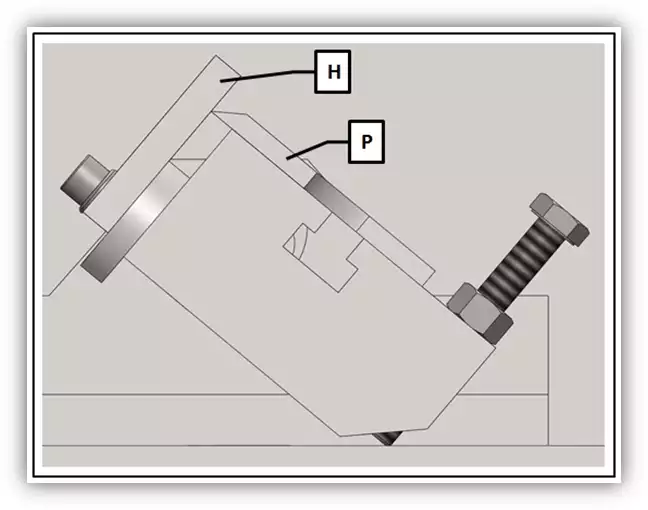
Figure 14
Put the knife to be sharpened on work plane A (see Figure 14) against alignment bar H (see Figure 14) on the side of the cutting edge. In this case too, if the model you purchased is not provided with alignment bars H use a comparator to carry out the alignment (see section 6.4.3).
6.4.3 Knife fastening
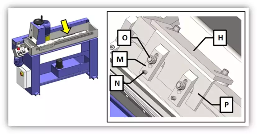
Figure 15
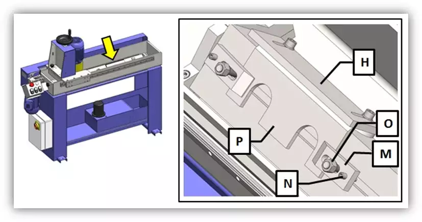
Figure 16
Fix knife P to work plane A (see Figure 12) using fixing brackets M in one of the two ways shown in Figure 15 and Figura 16. Align the bracket in relation to the knife plane using adjustment screws N (see Figura 15 and Figura 16). Now fasten fixing brackets M using nuts O (see Figura 15 and Figura 16). Before proceeding make sure the fixing brackets do not stick out of the knife sharpening plane. Unloose alignment bars H (optional see Figure 14), lower them and fasten them back again.
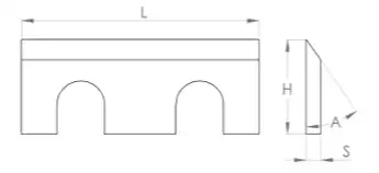
6.5. Table of operating characteristics.
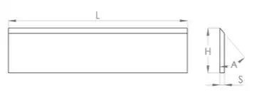
| PLANER KNIVES | |||
|---|---|---|---|
| Maximum length L (mm) | Cutting edge A (º) | Maximum height H (mm) | Thickness S (mm) |
| 650 | 40 | 35 | 3 |
| STANDARD KNIVES | |||
|---|---|---|---|
| Maximum length L (mm) | Cutting edge A (º) | Maximum height H (mm) | Thickness S (mm) |
| 650 | 40 | 35 | 3 |
NOTE:
It is strongly advised not to sharpen knives having different dimensions than those in the table. Our company disclaims all liability for any malfunction due to improper use of the machine.
7.WORK OPERATION
DANGER OF ACCIDENT
DANGER DUE TO SPARK PROJECTION
HAZARD FROM SHARP TOOLS
Warning: it is mandatory to use protective glasses and gloves. During sharpening pay attention to the movement of the carriage.
After positioning knives to be sharpened on the work plane (see section 8) knives can be sharpened. For a correct sharpening strictly follow the steps below.
7.1.Turning on the machine
Switch the knife grinding machine on by rotating the disconnect switch in a clockwise direction (Switch 6, Figure 3).
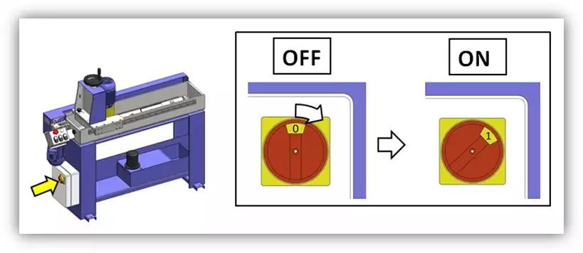
Figure 17
Make sure the machine is on by checking the indicating light on the control panel (Control panel 5, Figure 3) is on (see Figure 18).
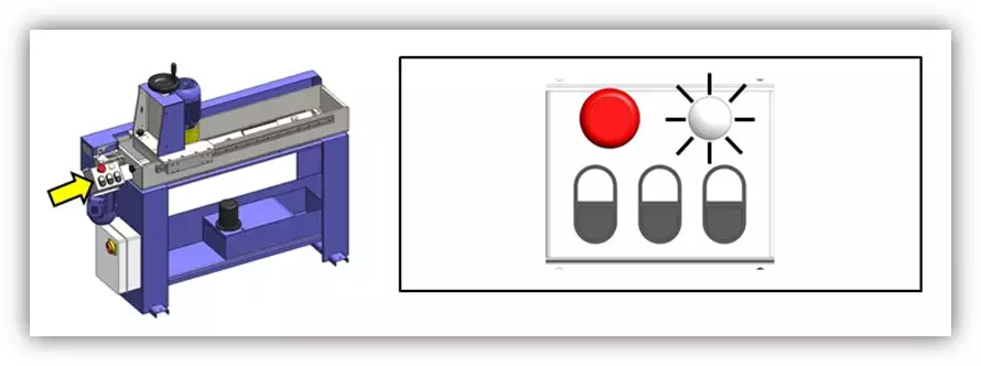
Figure 18
7.2 Grinding wheel positioning
Before starting the sharpening operation position the grinding wheel so as to prevent any impact. Once you have positioned the knives and set the work plane angle check the grinding wheel is in a higher position than knives to be sharpened. To position the grinding wheel follow the steps below.
Push the knob of the ratchet clutch 2 (see Figure 19) as shown in Figure 19. This will put the machine in neutral thus allowing you to manual adjust the grinding wheel.

Figure 19
Rotate handwheel 3 (see Figure 20) in a clockwise direction so as to make the grinding wheel move upwards. Lift the grinding wheel until it is above the knives and the work plane.

Figure 20
Now position the grinding wheel above the work plane. Press 1 on pushbutton 5B (see Figure 21) on the control board to activate the trolley movement 11 (see Figure 3); once the grinding wheel is above the knife to be sharpened press 0 on pushbutton 5B.
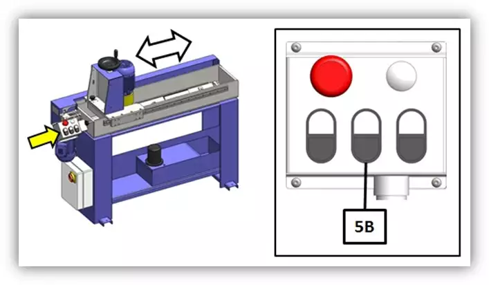
Figure 21
Rotate handwheel 3 (see Figure 22) in an anticlockwise direction to lower the grinding wheel until it touches slightly the surface of the knife to be sharpened.
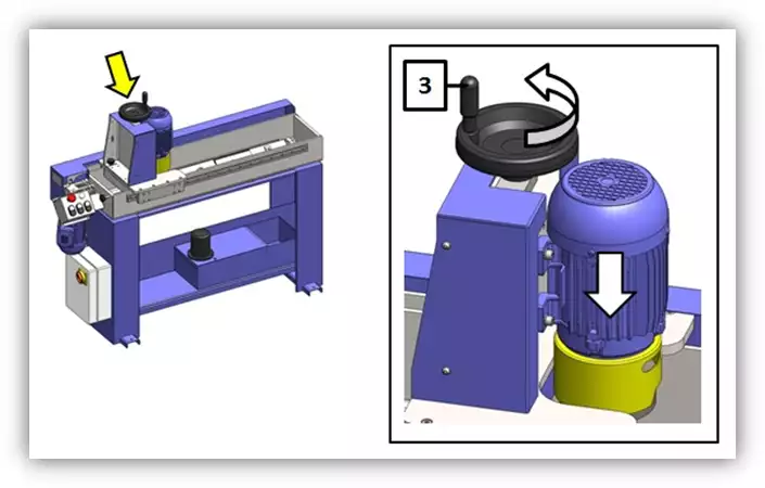
Figure 22
Disengage the ratchet clutch 2 (see Figure 23) pushing the knob as shown in Figure 23. This will re-establish the automatic movement of the grinding wheel.
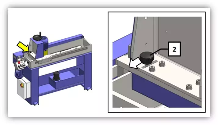
Figure 23
7.3. Adjustment of the grinding wheel automatic advance
First, make sure the ratchet clutch 2 (see Figure 23) is disengaged, otherwise disengage it. Then follow instructions below to adjust the grinding wheel advance, i.e. the quantity of material the grinding wheel shall remove at each pass.
By rotating knob 1 (see Figure 24) in a clockwise direction starting from position ‘0’, it is possible to increase the quantity of material the grinding wheel will remove at each pass. Advance goes from ‘0mm’ to ‘0.05mm’ which corresponds to the handwheel end of stroke.
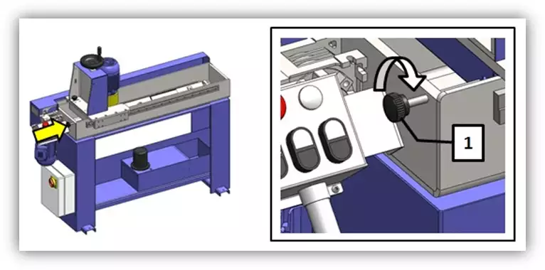
Figure 24
WARNING: It is advised to remove small quantities of material at each pass since excessive advance may overheat knives.
7.4. Adjustment of the grinding wheel manual infeed
First make sure the ratchet clutch 2 (see Figure 25) is engaged, otherwise engage it.
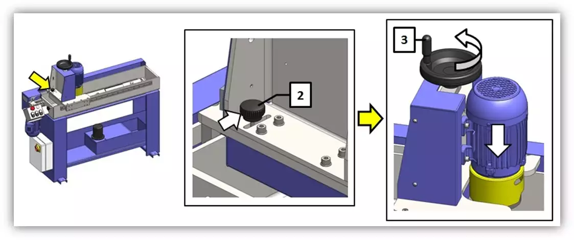
Figure 25
This operation will allow you to adjust the grinding wheel infeed using handwheel 3 (see Figure 25). Once the wheel rotation and the trolley sliding movement have been activated it will be possible to manually adjust the advance pass after pass.
7.5. Starting the grinding wheel rotation
Press pushbutton 5C (see Figure 26) to activate the grinding wheel rotation. When sharpening a knife, it is advised to activate the grinding wheel rotation first and then the trolley sliding movement to prevent the grinding wheel from hitting the knife to be sharpened when it is at a standstill.
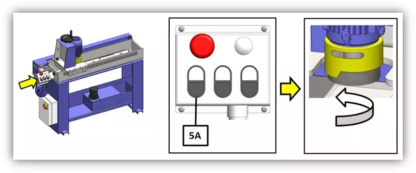
Figure 26
7.6. Starting the carriage sliding movement
Press pushbutton 5B (see Figure 27) to activate the carriage movement.
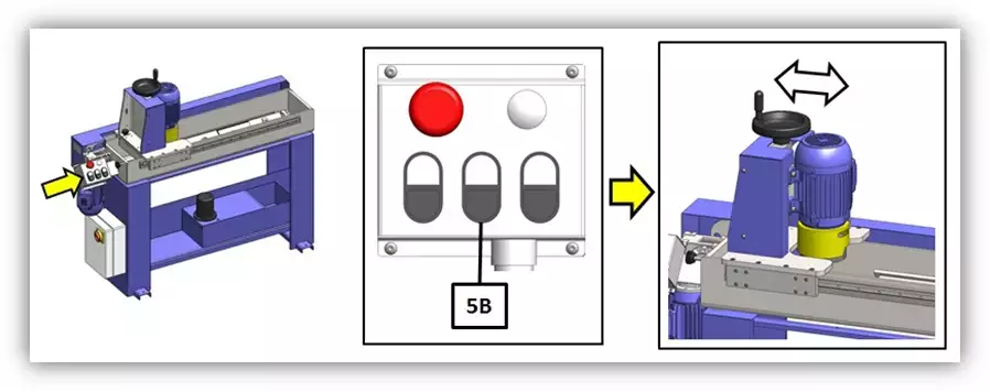
Figure 27
7.7. Starting the coolant pump
Press pushbutton 5A (see Figure 28) to allow the cooling fluid to flow.
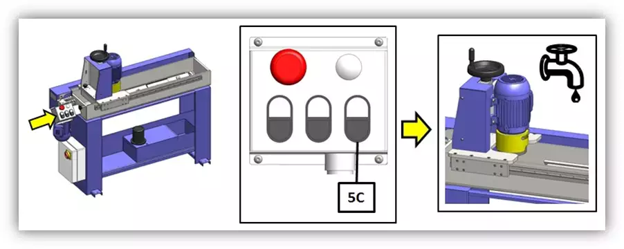
Figure 28
7.8. Safety system
Knife grinding machine KG650 (KG850) is provided with a safety system blocking the grinding wheel advance maximum every 0,5 mm. This means the sum of the following automatic advances will never exceed 0,5 mm. This shrewdness has been introduced to prevent the machine from keeping on sharpening in case it is left on and unattended, thus causing negative consequences. Therefore it may occasionally happen that the automatic advance blocks before the sharpening operation has been finished. Should this occur, make the grinding wheel advance manually using handwheel 3 (see Figure 3). Now the automatic infeed will re-start again for 0,5 mm. more.
You can repeat this operation until the knives are sharpened to the desirable amount.

Figure 29
7.9. Adjustment of grinding wheel inclination
If during working the grinding wheel touches the knife with its backside, its inclination can be adjusted using the two screws on the back of the trolley. First unloose the four clamp bolts (indicated by the dark arrows in Figura 30) then tighten the two adjustment screws (indicated by the light arrows in Figure 30) so as to increase the inclination of the wheel front. Tighten the clamp bolts.
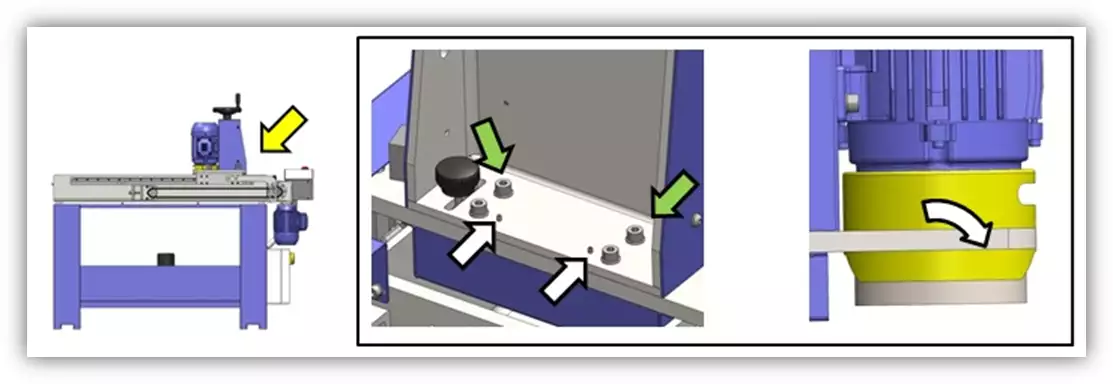
Figure 30
8. MAINTENANCE
8.1.Preventive maintenance
DANGER OF ACCIDENT
DANGER DUE TO SPARK PROJECTION
HAZARD FROM SHARP TOOLS
A careful periodical maintenance is essential to ensure ideal working conditions and efficiency. Moreover this will help extend the machine’s life.
| PERIODIC CHECKS | ||
|---|---|---|
| CONTROL TYPE | HOW | WHEN |
| Cleaning the blade holder | The work surface must be carefully cleaned to avoid the accumulation of residual material which could considerably compromise the operation of the machine, or at least reduce performance. It is recommended to clean with water mixed at 2% with emulsifiable cutting oil. | Daily |
| Tank cleaning | It is recommended to clean the tank to prevent the accumulation of residual material from affecting the correct operation of the machine or simply preventing the coolant from flowing normally. It is recommended to clean with water mixed at 2% with emulsifiable cutting oil. do not blow with compressed air. |
Periodically |
| Cleaning the gearmotor, refilling the oil | The gearmotor is covered by the casing 8 (see figure 3) and therefore must be removed after removing the 4 fixing screws. Check the gearmotor oil level and, if necessary, restore it. Check the chain tension and adjust it if necessary. |
If necessary |
| Cleaning and lubrication of the chain and gears | The chain and gears are covered by the casing 8 (see figure 3) and therefore must be removed after removing the 4 fixing screws. Check that the chain and gears do not have incrustations or deposits of residual material. clean with a cloth and grease. With wear, it may be necessary to replace both the chain and the sprockets. | Weekly |
| Chain tensioner adjustment | The chain tensioner is covered by the casing 8 (see figure 3) and therefore must be removed after removing the 4 fixing screws. Check the chain tension and adjust it if necessary (see chapter 11.3). | If necessary |
| Cleaning the sliding guides | It is recommended to carry out a daily check on the cleanliness of the carriage sliding guides. Any waste deposits must be cleaned so as not to compromise their efficiency. | Daily |
| Replacing the grinding wheel | The grinding wheel is subject to wear and therefore must be replaced periodically (for replacement, see section 8.2). | If necessary |
8.1.1 Grinding wheel replacement
When the wheel reaches its wear limit or when its condition does not guarantee a good level of sharpness, it will need to be replaced. To do this, proceed as indicated in the following steps:
Push the knob of the ratchet clutch 2 (see Figure 31) as shown in Figure 19. This will put the machine in neutral thus allowing you to manual adjust the grinding wheel.

Figure 31
Rotate handwheel 3 (see Figure 32) in a clockwise direction so as to make the grinding wheel move upwards. Lift the grinding wheel until the end of stroke.
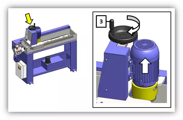
Figure 32
Now position the grinding wheel outside the work plane. Press 1 on pushbutton 5B (see Figure 21) on the control board to activate the trolley movement 11 (see Figure 3); once the grinding wheel is outside the work plane press 0 on pushbutton 5B.
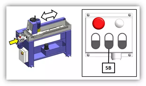
Figure 33
Use wrench 20 (see Figure 34) to block the grinding wheel motor shaft. To this end insert the wrench above mentioned in the slot in the grinding wheel guard and make it couple to the grinding wheel holder.
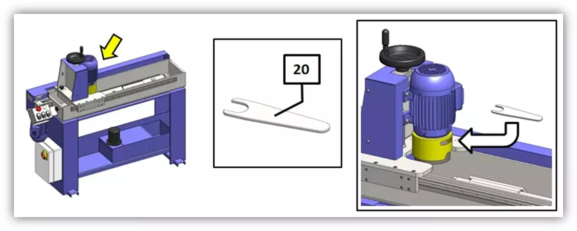
Figure 34
Now use the special wrench 21 (see Figure 35) provided with the machine to remove the grinding wheel. Position the wrench so that its two teeth are in the grinding wheel hollow. Once the wrench holds the two holes in the grinding wheel holder, hold wrench 20 tightly so as to block the grinding wheel rotation and unscrews the nut in the grinding wheel holder using wrench 21.
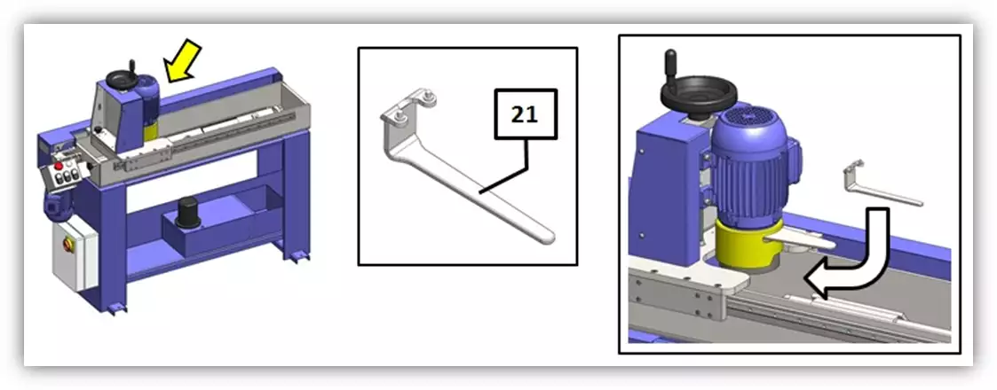
Figure 35
After unscrewing the nut on the grinding wheel holder remove the worn-out wheel and replace it with a new one. Screw the nut back on the grinding wheel holder using the two wrenches 20 and 21.
8.1.2 Removal of the chain guard for periodical maintenance
To carry out periodic maintenance of the chain, gears and reducer, the corresponding protection casing must be removed. To do this, it will be enough to remove the four fixing screws located in the areas indicated by the arrows in figure 36.
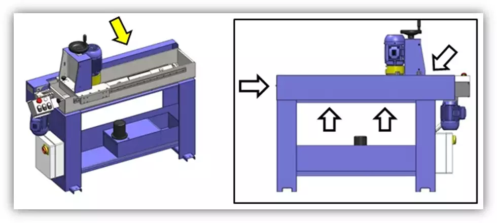
Figure 36
8.1.3 Chain tensioner adjustment
If you consider that the chain tension must be adjusted, proceed as indicated in the following points:
- Remove the safety guard as described in section 8.1.2;
- Unloose screws 22 and 23 shown in Figure 37;
- Unloose nut 24 as shown in Figure 37;
- Adjust the chain tension using nut 25 (Figure 37);
- After adjusting the chain tension screw nut 24, screw 22 and screw 23 back on.
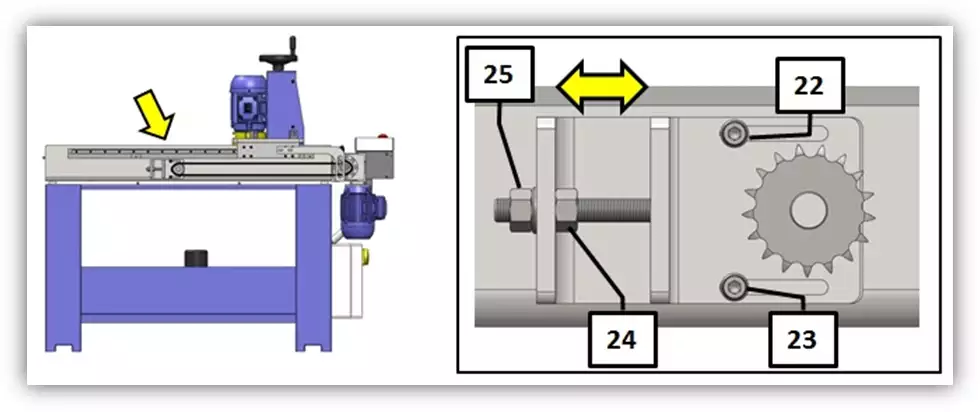
Figure 37
8.2. Problems and solutions
Problem: the machine does not turn on
Cause:
- Insufficient mains voltage. Solution: check the connection to the electrical network
- Defect of the disconnector. Solution: check the connection of the line disconnector. Check the operation of the line disconnector.
- Faulty auxiliary transformer. Solution: check that the auxiliary transformer fuse is not blown. Verify that the auxiliary transformer is working.
Problem: the grinding wheel motor does not rotate
Cause:
- The machine is turned off. Solution: turn on the machine with disconnector 6 (see figure 3, section 7.1)
- Emergency button 7 (see figure 3) activated: Solution: deactivate the emergency button
- Engine malfunction. Solution: contact a specialized technician for replacement
- Defect in the engine start button. Solution: Contact a specialized technician to replace the button
Problem: The grinding wheel does not rotate correctly
Cause:
- The wheel is mounted incorrectly. Solution: reassemble the wheel in the correct way
- Unbalanced wheel: Solution: check the condition of the fixing holes and replace the wheel if necessary (see section 8.1.1)
Problem: The car does not start
Cause:
- The machine is turned off. Solution: turn on the machine with disconnector 6 (see figure 3, section 7.1)
- Emergency button 7 (see figure 3) activated. Solution: deactivate the emergency button
- Engine malfunction. Solution: contact a specialized technician to replace the reducer
- Broken chain. Solution: replace the chain (see section 8.1.2)
- Chain disengaged. Solution: re-engage the chain (see section 8.1.2)
- Bolt not inserted into trailing arm. Solution: reinsert the bolt into the specific housing on the arm (see section 8.1.2)
- Defect in the gearmotor start button. Solution: Contact a specialized technician to replace the button.
Problem: Poor sliding of the wheel feed wheel
Cause:
- The screw and block are dirty or excessively worn. Solution: clean or replace
- Jack clutch knob is disengaged. Solution: engage the jack clutch (see section 7.3)
- The vertical slide guides are dirty. Solution: clean the guides
Problem: Poor carriage sliding
Cause:
- Carriage slide guides are dirty. Solution: clean the guides properly
Problem: The reducer leaks oil
Cause:
- The reducer oil seal is defective. Solution: replace the seal and restore the oil level
Problem: The blades are not sharpened correctly at the end of machining
Cause:
- Blades are not aligned correctly. Solution: align the blades correctly (see section 6)
- The cooling system is not working properly and therefore the blades are not cooled sufficiently. Solution: check the cooling system and, especially, the direction of the nozzles through which the liquid comes out
- The wheel is excessively worn. Solution: sharpen the wheel or replace it if necessary (see section 8.1.1)
- The vertical feed of the grinding wheel does not work correctly. Solution: the automatic vertical feed of the grinding wheel is not correctly regulated (see section 7). The screw that guarantees advance could be excessively worn and must therefore be replaced.
9.ACCESSORIES AND CONSUMABLES
10.GUARANTEE
All our machines are tested before being shipped. However, there can always be defects that are not observable at first sight.
Our machines are guaranteed against manufacturing or material defects under normal use and maintenance conditions.
The period of this guarantee is 12 months from the date of purchase and consists of the replacement of defective material.
The guarantee will be automatically canceled in the event of a modification outside our company. Or in manifest cases of misuse of the machine.
The guarantee does not include parts subject to normal wear due to use such as skids, lubrication cartridge, abrasives, etc.
11.DOWNLOAD MANUAL
ES - User Manual CU mini 650.pdf
12.FAQ
Question nr1
Answer no. 1