1.FIRST STEPS
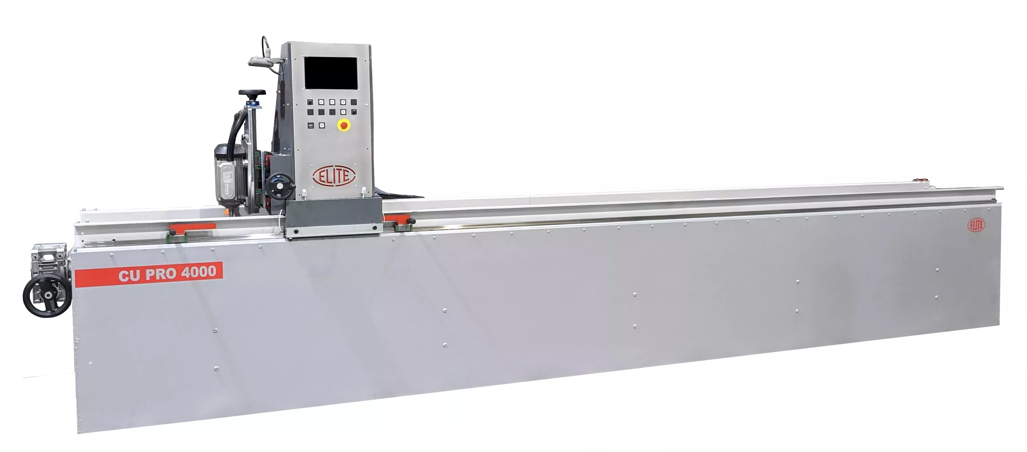
Congratulations on your purchase of the ELITE model CU PRO knife grinding machine.
Read this guide before you start.
The ELITE CU PRO model is our most advanced blade manufacturing and sharpening machine. It features a vibration dampening base and grinding head and equips a direct drive motor: this allows it to have up to 20% more engine motor power compared to other motors that incorporate a belt transmission. Its design and programming make it possible to optimize grinding work in an agile and safe way.
You can view the product catalog at the following link: ELITE model CU PRO
This manual introduces you to the main functions of the grinder in order to avoid risks to your health or that may cause a breakdown or premature wear of the machine.
In case of any doubt, please contact us directly or one of our authorized distributors.
Informative Note: The use described in the manual of this knife grinder described therein may present some variations in use as our machinery is subject to possible construction modifications, depending on the incorporation of technological advances in our sharpening equipment.
2.SAFETY
2.1.Safety regulations
Carefully observe and apply the following safety rules, not respecting these rules may cause personal injury or damage to the machine itself.
The installation and maintenance of the machine described in this manual must be carried out only by operators who are familiar with its operation and have sufficient technical knowledge.
The ELITE model CU PRO have been designed for the sharpening and grinding of knives, excluding any other type of operation.
DANGER HIGH VOLTAGE

DANGER OF ACCIDENT

DANGER DUE TO SPARK PROJECTION

WEAR PROTECTIVE SHOES

DANGER FROM SHARP TOOLS

USE HEARING PROTECTORS
These warnings do not include all possible risks that improper use of the machine could cause. For this reason, the operator must proceed with prudence and observing the rules.
2.2.Use and storage of the instruction manual
This instruction manual must be read and understood by all personnel who come into contact with the machine.
This manual is for:
- Indicate the correct use of the machine according to the type of work to be carried out.
- Provide the necessary instructions for the transport, adjustment and maintenance of the machine.
- Facilitate the ordering of spare parts and information on risks.
Limits of use of the manual:
The machine is intended for professional use and therefore the experience of the operator is required and of vital importance.
Importance and conservation of the manual:
This manual must be considered part of the machine and must therefore be attached to it until the end of its use.
Additional information and clarifications:
The user, owner or maintenance person can contact the manufacturer to request any additional information on the use of the machine and possible modalities for maintenance and repair intervention.
Expiration of responsibility:
The manufacturer is considered exempt from any liability in the event of:
- Improper use of the machine
- Use of the machine by untrained persons
- Serious failures in scheduled maintenance
- Unauthorized interventions or modifications
- Use of non-original spare parts.
2.3.Declaration of conformity
The company hereby:
Elite Machines, SLU
Joan Oró, 27
ES-08635 Sant Esteve Sesrovires
declares that the product indicated below, based on its conception and construction, as well as the version put on the market by our company, complies with the mandatory basic health and safety requirements of the CE directive.
This declaration loses its validity in the event of unauthorized modifications to the product.
Product name: ELITE CU PRO
Product type: Sharpening and grinding knife machine
Serial No.: __
EC Directive Competences:
- EC Machinery Directive (2006/42/EC)
- European directive on electromagnetic compatibility (2014/30/EU)
- The protection purposes of the CE low voltage directive (2006/95/CE) were fulfilled according to annex I, nr. 1.5.1 of the machinery directive 2006/42/EC
The technical documentation was compiled by Legal representative of the documentation:
Sergi Valls Gramunt
Joan Oró, 27
ES-08635 Sant Esteve Sesrovires
Date / manufacturer - Signature: __
Signatory data: Sergi Valls Gramunt, manager
3.TECHNICAL DATA
In the following information table, find the list of technical specifications of the machine described in this manual.
| TECHNICAL DATA | CU PRO |
|---|---|
| Grinding wheel motor power | Direct drive 15 HP for 50Hz - 18HP for 60Hz - 1500 RPM Optional: 20 or 30 HP. |
| Grinding wheel diameter | ø250 mm. (Optional ø300 mm.) |
| Carriage speed | From 1 to 30 m/min. |
| Max. distance between grinding wheel and chuck | 180 mm. |
| Magnetic chuck wide | 180 mm. (Optional: 250 mm. and 300 mm.) |
| Coolant tank | 220 liters with mechanic separation |
| Max. connected power | 16 kW (21 kW for 20 HP, 32 kW for 30 HP motor) |
| Rotation movement of the magnetic clamping plate | from 0º to 90º |
| AVAILABLE VERSIONS | |||
|---|---|---|---|
| Model | Magnetic chuck size | Size | Weight |
| CU PRO 1000 | 1000 x 180 mm. | 2200 x 1200 x 1800 mm. | 1090 Kg. |
| CU PRO 1500 | 1500 x 180 mm. | 2700 x 1200 x 1800 mm. | 1580 Kg. |
| CU PRO 2000 | 2030 x 180 mm. | 3200 x 1200 x 1800 mm. | 2080 Kg. |
| CU PRO 3000 | 3060 x 180 mm. | 4200 x 1200 x 1800 mm. | 3080 Kg. |
| CU PRO 4000 | 4090 x 180 mm. | 5200 x 1200 x 1800 mm. | 3460 Kg. |
| CU PRO 5000 | 5120 x 180 mm. | 6200 x 1200 x 1800 mm. | 4880 Kg. |
| CU PRO 6000 | 6150 x 180 mm. | 7200 x 1200 x 1800 mm. | 4680 Kg. |
TECHNICAL REQUIREMENTS
- Connection voltage: 400V 3Ph 50Hz - 480V 3Ph 60Hz - 220V 3Ph 60Hz
- Required connection power: 16 kW
4.TRANSPORT
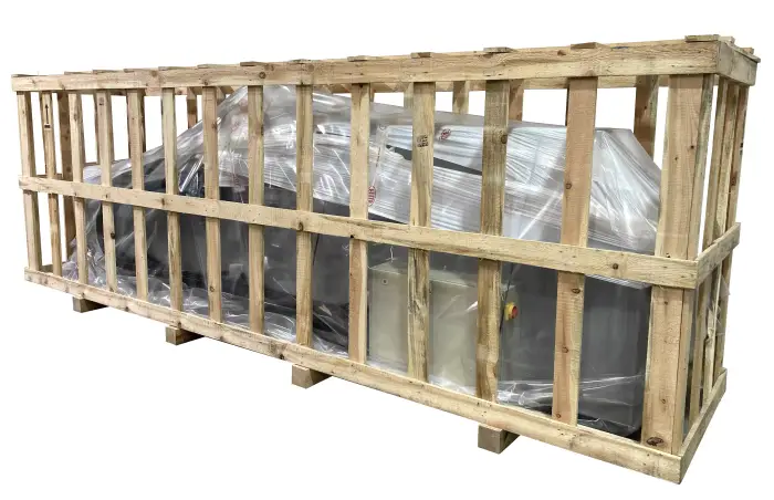
The ELITE model CU PRO is delivered packed in wooden jail.
During all transport and transfer, the machine must be kept in its original vertical position, any variation in this position may lead to the loss of the guarantee.
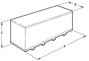
| Machine model | A (mm) | B (mm) | C (mm) | Weight (kg) |
|---|---|---|---|---|
| CU PRO 1000 | 2550 | 1350 | 1950 | 1305 Kg. |
| CU PRO 1500 | 3150 | 1350 | 1950 | 1730 Kg. |
| CU PRO 2000 | 3900 | 1350 | 1950 | 2230 Kg. |
| CU PRO 3000 | 4950 | 1350 | 1950 | 3230 Kg. |
| CU PRO 4000 | 5900 | 1350 | 1950 | 3630 Kg. |
| CU PRO 5000 | 6500 | 1350 | 1950 | 4050 Kg. |
| CU PRO 6000 | 7500 | 1350 | 1950 | 4850 Kg. |
4.1.Instructions for unpacking and setting up
Take special care when lifting the load: The load may not be centered! To do this, use a forklift with blades long enough to support the machine, taking into account the width and depth of the machine for the calculation of the weights to lift.
Approximate gross weight of the machine (may vary depending on the equipment supplied):
| Machine model | Weight (kg) |
|---|---|
| CU PRO 1000 | 1305 Kg. |
| CU PRO 1500 | 1730 Kg. |
| CU PRO 2000 | 2230 Kg. |
| CU PRO 3000 | 3230 Kg. |
| CU PRO 4000 | 3630 Kg. |
| CU PRO 5000 | 4050 Kg. |
| CU PRO 6000 | 4850 Kg. |
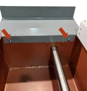
To disassemble the packaging, remove only the 4 sides and the roof. Do not remove the wood from the feet (indicated in the photo with red arrows).

The machine is delivered with the base fixed to the lower wood for its transfer.
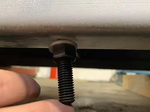
First, place the machine in its final location. Then remove the M12 hex bolts from the transport angle as shown in the following image.
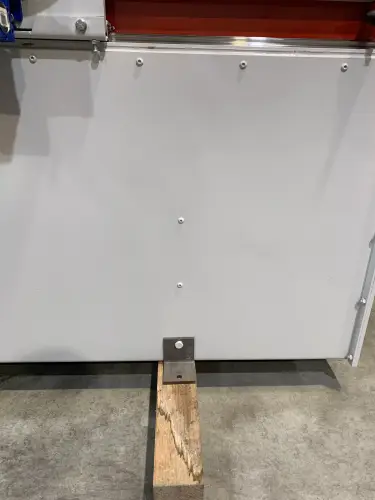
Once the transport angle has been removed, put the M12 hexagon bolt back into place and tighten it.
Repeat this operation for all transport angles.
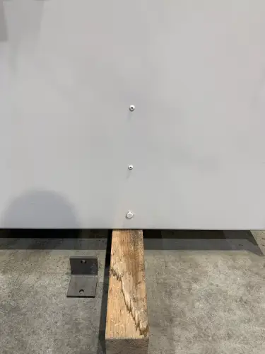
With the help of a hoist or a forklift, raise the machine to be able to move the wood to one side.
IMPORTANT: For your safety, do not remove the wood yet.
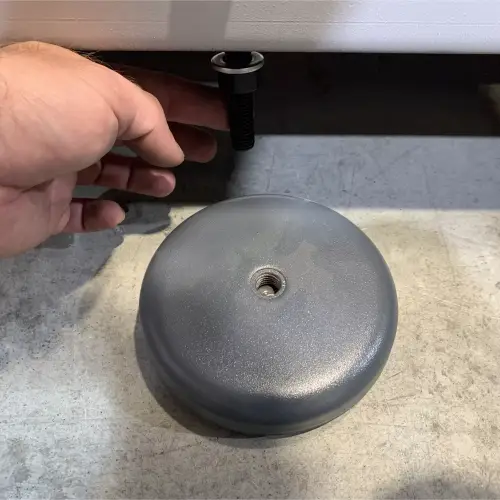
Use the supplied anti-vibration mounts to mount to and balance the machine.
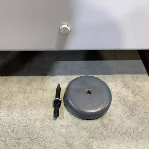
Just below the machine, where the M12 hex bolt we removed earlier, are the mounting holes for the anti-vibration mounts.
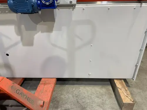
First insert the M12 stud with the nut and washer as shown in the photo.
Once the stud is in place and adjusted to the required size, we can now thread the support.
Support threaded on the M12 stud.
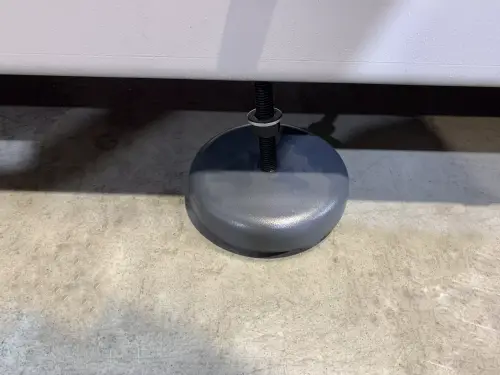
Now tighten the M12 nut to the position needed to free the wood and the forklift.
M12 nut in position.
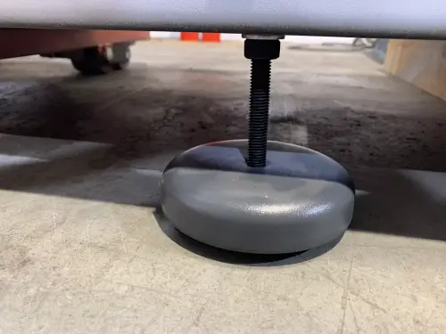
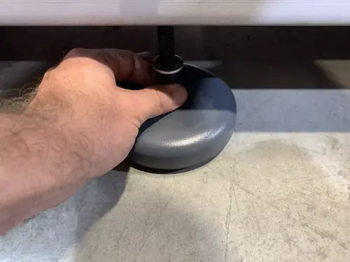
Once all the supports are in place, you can lower the forklift and remove the timbers.
Then you need to adjust the M12 nuts to the height you need to work.
NOTE: A lower position is more comfortable for loading/unloading the blades, and the machine is more stable.
Once the machine is located in its final location, you can now remove the protective film and other protections for components, which fixes and prevents the carriage from moving.
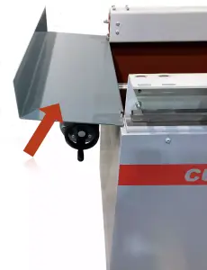
If the side tray is not assembled, assemble it by screwing in the two side screws as shown in the following picture:
5.INSTALLATION
5.1.Machine placement
Before any work we must make sure that the machine is well aligned and does not oscillate at any of its ends, in which case it must be wedged to avoid movements.
The machine must be perfectly level in the depth position (front-rear).
In the transversal position (left-right) it must have a slight drop towards the side where the coolant is evacuated, to better drain the machine bed towards the tank.
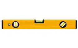
For its correct level it is necessary to use a spirit level. This check must be carried out both longitudinally and transversally.
Poorly leveling the machine can cause unwanted vibrations and premature wear of the linear guides.
WARNING: The machine must not be used under any circumstances by unqualified or unauthorized personnel.
5.2.Electrical connection
DANGER HIGH VOLTAGE!
Remember: before connecting the machine, remove any protection that the machine may have to protect the components during transport.
The ELITE model CU PRO grinding machine must be strictly connected to the voltage indicated in the machine order and on the machine itself. The connection to a voltage other than that indicated may cause a breakdown in the machine and represents a risk for people who use the machine.
This installation must be carried out by qualified technical personnel and checked with a voltage meter before turning on the machine.
It is absolutely essential that the cross-section of the connection cable is as required, that the machine has a dedicated outlet and is protected against overloads and shunts, and that it is as close as possible to the electrical outlet.
The electrical connection terminals have a red tape to facilitate correct connection.
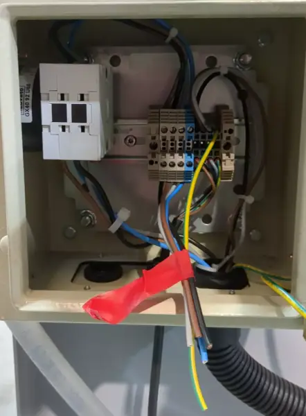
ELITE does not assume any responsibility in the event of an incorrect electrical installation that may cause a malfunction of the machine and even personal or material damage.
5.3.Main components of the machine
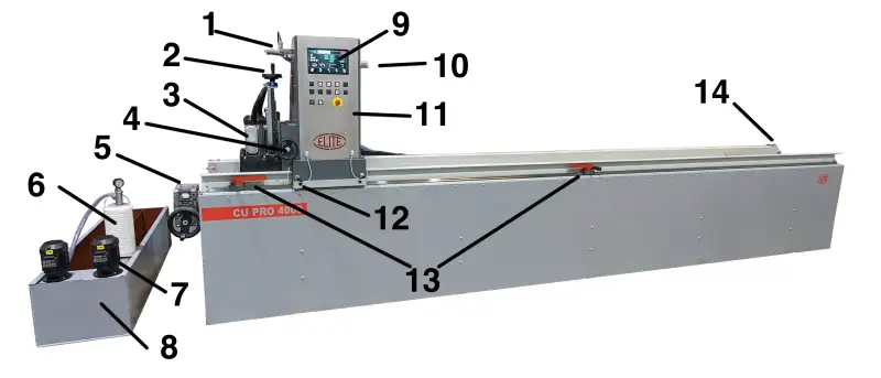
- Led light
- Manual adjustment of the raising or lowering of the second grinding wheel (optional)
- Second grinding wheel motor (optional)
- Regulation of the depth of the second grinding wheel motor (optional)
- Adjustment of the inclination of the magnetic chucks
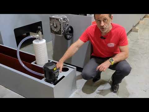
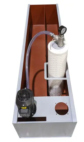
- FILTRAmaq UNO filtration system (optional)
- Coolant pump motor (optional)
- Cooling tank (optional)
- LCD Screen
- Manual adjustment of the raising or lowering of the grinding wheel
- Control panel
- Adjustment of the inclination of the main grinding wheel motor
- Carriage travel adjustment stops
- Carriage belt tension adjustment
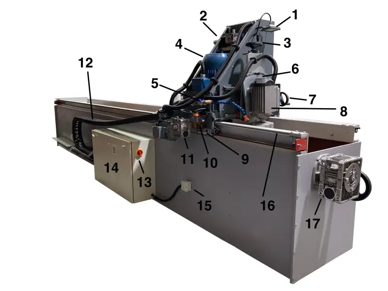
- Led light
- Manual lowering of the main grinding wheel
- Manual lowering of the Z2 axis of the second grinding wheel motor (optional)
- Grinding wheel main motor
- Regulation of the coolant flow
- Adjustment of the inclination of the second grinding wheel motor (optional)
- Adjustment of the depth travel of the second grinding wheel motor (optional)
- Second grinding wheel motor (optional)
- Regulation of the inclination of the main motor of the grinding wheel
- Manual centralized greasing
- Carriage reducer motor
- Transport chain for power cables
- Main switch
- Electrical panel
- Connection box for magnetic plates
- Carriage movement toothed belt
- Adjustment of the inclination of the magnetic chucks
5.4.Control panel
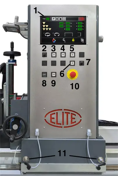
- LCD screen
- Carriage speed selector
- Carriage movement to the left
- Carriage movement to the right
- Z axis up
- Z axis down
- Speed regulator of second grinding wheel (optional)
- START button
- STOP button
- Emergency stop
6.STARTING UP
In this section we show you how to operate the ELITE CU PRO in order to work.
NOTE: The data that appears in the different images are by way of example, each type of tool has its recommended data and a skilled operator must know them.
Emergency stop
It's the round red button. In the event that there is a failure in use or a dangerous situation is being created, it allows the immediately disconnection of the machine.
Should not be used unless strictly necessary.
Once used, to use the machine again, you must pull it to return to the initial position, additional referencing and setting up must be needed.
WARNING: Under no circumstances should this control be modified or manipulated, this automatically puts the operator and people around him in danger of serious injury.
6.1 Set up
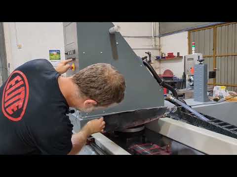
Once you receive the ELITE CU PRO, the first thing to do is to remove the cooling tank that is inserted inside the machine bed. Likewise, the grinding wheels are also supported on the magnetic plate so that the spindle do not move or suffer from vibrations during transport.
Now, connect it to the voltage that the machine has requested. It is important to have a qualified electrician connect the machine according to local regulations.
Important: once you turn it on, raise the axes to release them !!
Once the grinding machine is installed, you can turn it on, using the main switch on the back, and then deactivate the emergency stop.
Once we do this, in the LCD screen, the introductory video to the menu appears.
Press the screen to see the programs. There are 6 options in the upper part of the screen. All the information is here.
On the lower part you have the magnets ON/OFF, coolant ON/OFF, light lamp and save program. Once we introduce the desired changes of the program, save the program.
Simply press on the icon selected. In case of the magnetization icon, you need to press for at least 2 seconds.
Important: in order to not overheat the coils of the magnets, it is needed to wait few seconds between magnetization and demagnetization !!
In the options screen, we have the configuration screen, the machine aproximation to the knive before automatic program starts, and the screen that informs us of how the automatic program progress.
In this case, since no automatic program is being executed, it does not tell us any information. If the machine were sharpening, it would indicate the phase it is in and the time it has been sharpening.
While the machine is sharpening we can see the other screens or even carry out a different program.
How does it work? The up arrow down arrow buttons are to raise or lower the grinding wheel.
We can do it with the buttons or manually to make a fine adjustment
The left right buttons are to move the carriage.
The carriage will move until it finds one of the side stops.
Once the end is reached we cannot move more. We can adjust the stops to the size that interests us and by means of this potentiometer we can regulate the speed of the carriage, either in manual movement or in automatic movement, as we will now see.
We can carry out this adjustment at any time.
Finally, the second potentiometer, which is optional, It is to regulate the rotation speed of the second grinding wheel motor, which is also optional on the machine.
The rotation speed of the second motor of the grinding wheel can be regulated because it is very important, since we use the second motor of the grinding wheel above all for very fine finishing phases.
We can regulate this motor both longitudinally and in height but the descent of this is manual, it does not work with the automatic program
We can also adjust, using a 19 key, the inclination.
This inclination, normally, we select a small difference with respect to the degrees of the magnetic chuck or absolutely straight. Because it is used many times when we have a double angle blade. So if the blade had 25 degrees on one edge and 30 on the other, we would put 25 degrees on the chuck and 5 degrees on the second grinding motor to be able to do both sides at the same time.
Once we have it, we fix the screw.
To be able to regulate the inclination of the magnetic chuck, we have this divider.
In this graduated scale here, it indicates the degrees from 0 to 90.
To be able to adjust it, simply rotate the knob. We turn it and at the same time that the needle turns, the plate rotates.
In the event that we like to work backwards from 90 to 0, we can loosen the needle when it is at 0 and we would put it at 90 to make the reverse path.
At the back of the machine we have the carriage belt, this must be sufficiently tight, but not too much. If it is not too tight, the sprocket can come out of the belt and the carriage will skid. But if it is too tight, the sprocket and belt will wear out prematurely.
For the tensioning operation we will do it in this part here using the tensioner. We would just loosen the screws of the fixing support and we would tighten or loosen it with this stud
Once the operation has been carried out, we tighten again and we have set up.
Finally, remember that once a week or so, give a few impulses to the grease pump that will grease the 4 skids of the carriage as well as the ball screw of the vertical ballscrew.
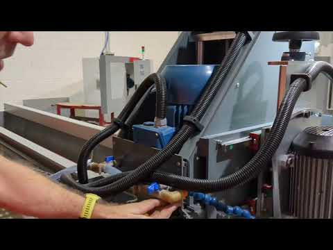
Also on the back of the machine carriage we have the regulation of the coolant flow both of the second motor of the grinding wheel, in case it is included as an option, and of the two water outlets that have the left and right side of the the main grinding motor.
The system for centering the blades along the edge is available as an option.
This system consists of a centering point on each plate. This centering point is always hidden so that we can set the blade at the height we want. But when we want to sharpen several blades at the same time to the same measurement, what we do is release the centering device, raise it, and thus we have a reference for all the blades.
Once the blade is referenced, we magnetize the plate and we have it fixed. Then we must lower the centering tool.
Now, when we go to sharpen the blade, we already have it centered
Regarding the sharpening program:
To carry out a sharpening program we simply introduce the roughing values, that we have seen in the video of start-up, finishing and lapping. In the event that there is one of the operations that we do not want to perform, we simply leave the value at 0 and it will not do it. We select which of the two motors must rotate, or both at the same time, and towards which direction of rotation. And where we want the in-feed load to be applied: left, right or both sides.
And also if we want we can set the grinding wheel to stay down when the grinding program is finished. Or return to recover the previous position to make another set of blades at the same height.
6.2 Control panel

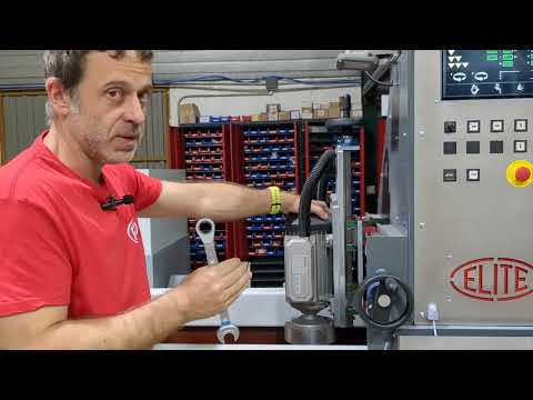
6.3 Mounting and disassembling of the grinding wheel
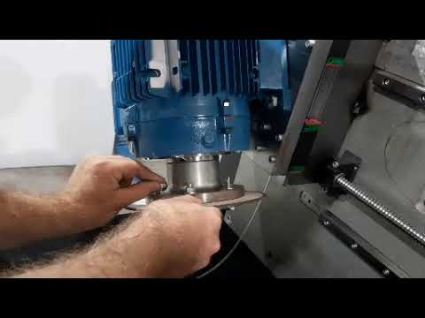
6.3.1 Mounting and dismounting the grinding wheel of the second head with automatic lowering
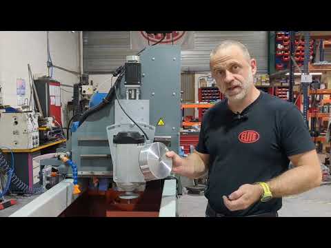
6.4 Assembly of the ring gear holder
6.5 Sharpening operation
To start the sharpening process, you must first make sure that the emergency stop button is not activated.
WARNING: never manipulate the buttons on the control panel while changing the abrasive wheel: danger of very serious injuries. It is highly recommended to switch off and disconnect from power mains the machine when working inside the machine. Under no circumstances should the wheel be started while someone is handling it.
6.6 How to grind flat blades
6.7 Cooling system
6.8 How to regulate coolant flow

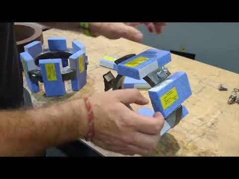
6.9 How to change the segments of the segment holder

6.10 Grinding wheel quick change system

6.11 How the safety light curtain works

7.WORK OPERATION
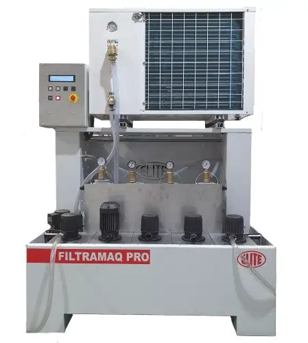
Working example of the CU PRO 4000 grinding the chuck with the FILTRAmaq PRO cooling system

7.1. How to demagnetizer blades and tools
If the blades or tools become magnetized by the magnetic plates, we can use the ELITE demagnetizer to eliminate the remnants (optional accessory).

8.MAINTENANCE
8.1.Preventive maintenance
The maintenance of the ELITE model CU PRO is very simple but at the same time important.
It consists of the following:
- Cleaning of the carriage guides - Daily
- Cleaning and greasing the grinding chuck, in case the machine is not used for several days, to prevent oxidation.
- Check the level of coolant in the tank, using the coolant recommended by ELITE: SintoCut MIX for steel and ELITE SintoCut PRO MIX for steel + tungsten carbide. The coolant mixture should be made with water at a proportion between 2 and 8% of SintoCut. Being below it can lead to oxidation of mechanical parts and if the level is higher it can be toxic.
- Remove the sludge that is deposited both in the work area and in the coolant - Daily.
- Grease the carriage slide bearings by means of the greasing nipples - Monthly.
- Keeping the machine clean and in good condition will allow for optimal long-term use.
Use the equipment only in dry environments. The temperature must be between 5 and 40ºC. A relative humidity greater than 90%, as well as a saline environment, would cause premature corrosion of the machine.
8.2 Lubrication of bearings and spindle
9.ACCESSORIES AND CONSUMABLES
9.1.Grinding wheels
9.1.1.Grinding wheel for carbide knives
We recommend to use ELITE ref. nr. 3050-A. 6A2 Diamond ø250x6x3x50x127 mm.
9.1.2.Grinding wheel for HSS knives
We recommend to use ELITE ref. nr. 3150-A. 6A2H CBN ø250x6x6x3x50xø127 mm.
9.1.3.Grinding wheel for steel knives
We recommend to use ELITE ref. nr. 3651-A. 6A2 Corundum ø250x100xø127
9.2.Coolant agents
9.2.1.Working for carbide or steel / HSS
We recommend to use ELITE SintoCut PRO MIX 200L or 20L or equivalent
9.2.2.Working with steel and HSS
We recommend to use ELITE SintoCut MIX 20 L or equivalent.
9.3.Equipment
9.3.1.Filtering systems
Machine could be equipped with one of the following ELITE filtering systems. If your machine already has one of this systems and you need information or help, please refer to the manual of the filtering system.
9.3.1.1.FILTRAmaq UNO
An autonomous equipment for the filtration of grinding/sharpening liquids, up to 2µm. It is ready to be installed inside the tank of ELITE model machines like CU or CU PRO.
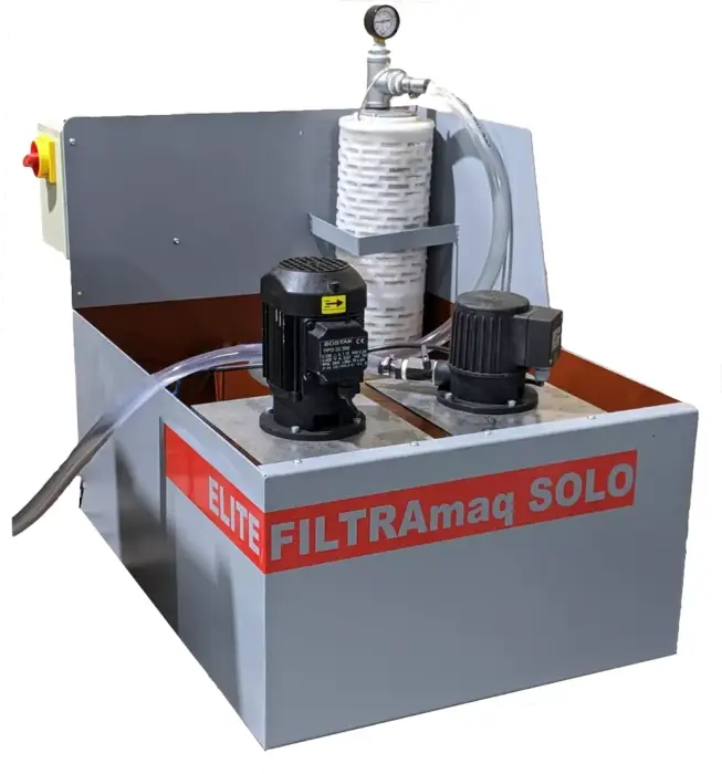
9.3.1.2.FILTRAmaq SOLO
Independent filtering system for one machine.
9.3.1.3.FILTRAmaq PRO
Centralized filtering system for up to 5 machines.
10.WARRANTY
All our machines are tested before being shipped. However, there can always be defects that are not observable with the naked eye.
Our machines are guaranteed against manufacturing or material defects under normal use and maintenance conditions.
The period of this guarantee is 12 months from the date of purchase and consists of the replacement of defective material.
The guarantee will be automatically canceled in the event of a modification outside our company. Or in manifest cases of misuse of the machine.
The guarantee does not include parts subject to normal wear due to use such as skids, lubrication cartridge, abrasives, etc.
11. DOWNLOAD USER MANUAL
12.FAQ
Question nr1
Answer no. 1