1.FIRST STEPS
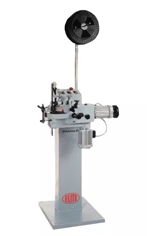
Congratulations on your purchase of the ELITE model SC 2 bandsaw and circular saws sharpening machine.
Read this guide before you start.
The SC 2 is a bandsaws and circular saw blade automatic sharpening machine with low maintenance. For straight tooth and spaced straight tooth sharpening and setting in band saws from 10 up to 70 mm wide (0,4" to 2-3/4")
It also allows to sharpen steel or CV circular saw blades from 110 up to 600 mm (4-1/3" to 25,5")
You can view the product catalog at the following link: ELITE model SC 2
This manual introduces you to the main functions of the grinder in order to avoid risks to your health or that may cause a breakdown or premature wear of the machine.
In case of any doubt, please contact us or one of our authorized distributors.
Informative Note: The use described in the manual of this circular saw blade sharpening machine described therein may present some variations in use as our machinery is subject to possible construction modifications, depending on the incorporation of technological advances in our sharpening equipment.
2.SAFETY
2.1.Safety regulations
Carefully observe and apply the following safety rules, not respecting these rules may cause personal injury or damage to the machine itself.
The installation and maintenance of the machine described in this manual must be carried out only by operators who are familiar with its operation and have sufficient technical knowledge.
The ELITE sharpening machines of the SC 2 model range have been designed for the sharpening of band and circular saw excluding any other type of operation.

DANGER HIGH VOLTAGE

DANGER OF ACCIDENT

DANGER DUE TO SPARK PROJECTION

WEAR PROTECTIVE SHOES

DANGER FROM SHARP TOOLS

USE HEARING PROTECTORS
These warnings do not include all possible risks that improper use of the machine could cause. For this reason, the operator must proceed with prudence and observing the rules.
2.2.Use and storage of the instruction manual
This instruction manual must be read and understood by all personnel who come into contact with the machine.
This manual is for:
- Indicate the correct use of the machine according to the type of work to be carried out.
- Provide the necessary instructions for the transport, adjustment and maintenance of the machine.
- Facilitate the ordering of spare parts and information of risks.
Limits of use of the manual:
The machine is intended for professional use and therefore the experience of the operator is required and of vital importance.
Importance and conservation of the manual:
This manual must be considered part of the machine and must therefore be attached to it until the end of its use.
Additional information and clarifications:
The user, owner or maintenance person can contact the manufacturer to request any additional information on the use of the machine and possible modalities for maintenance and repair intervention.
Expiration of responsibility:
The manufacturer is considered exempt from any liability in the event of:
- Improper use of the machine
- Use of the machine by untrained persons
- Serious failures in scheduled maintenance
- Unauthorized interventions or modifications
- Use of non-original spare parts.
2.3.Declaration of conformity
The company hereby:
Elite Machines, SLU
Joan Oró, 27
ES-08635 Sant Esteve Sesrovires
Declares that the product indicated below, based on its conception and construction, as well as the version put on the market by our company, complies with the mandatory basic health and safety requirements of the CE directive.
This declaration loses its validity in the event of unauthorized modifications to the product.
Product name: ELITE model SC 2
Product type: Automatic band and circular saws sharpening machine
Serial No.: __
EC Directive Competences:
- EC Machinery Directive (2006/42/EC)
- European directive on electromagnetic compatibility (2014/30/EU)
- The protection purposes of the CE low voltage directive (2006/95/CE) were fulfilled according to annex I, nr. 1.5.1 of the machinery directive 2006/42/EC
The technical documentation was compiled by legal representative of the documentation:
Sergi Valls Gramunt
Joan Oró, 27
ES-08635 Sant Esteve Sesrovires
Date / manufacturer - Signature: __
Signatory data: Sergi Valls Gramunt, manager
3.TECHNICAL DATA
In the following information table, find the list of technical specifications of the sharpening machine described in this manual.
| TECHNICAL DATA | ELITE SC 2 |
|---|---|
| Band saw width | From 10 to 70 mm. (0.39" to 2.75") |
| Band saw thickness | From 0.5 to 1.5 mm. (0.019" to 0.06") |
| Tooth pitch | From 5 to 30 mm. (0.19" to 1.18") |
| Tooth profile | Straight and spaced straight |
| Working speed | 54 teeth/minute. Optionally available with electronic speed regulator from 10 to 60 teeth/minute. |
| Grinding wheel RPM | Aprox. 3000 RPM |
| Grinding wheel motor | 0.55 kW |
| Saw blade diameter | From 110 to 600 mm. (4.3" to 23.6") |
| AVAILABLE VERSIONS | ||
|---|---|---|
| Model | Packing Size | Weight |
| SC 2 | 980 x 810 x 1710 mm. | 122 kg |
| SC 2 + TR 2 | 980 x 810 x 1710 mm. | 150 kg |
| SC 2 + TR 3 | 980 x 810 x 1710 mm. | 180 kg |
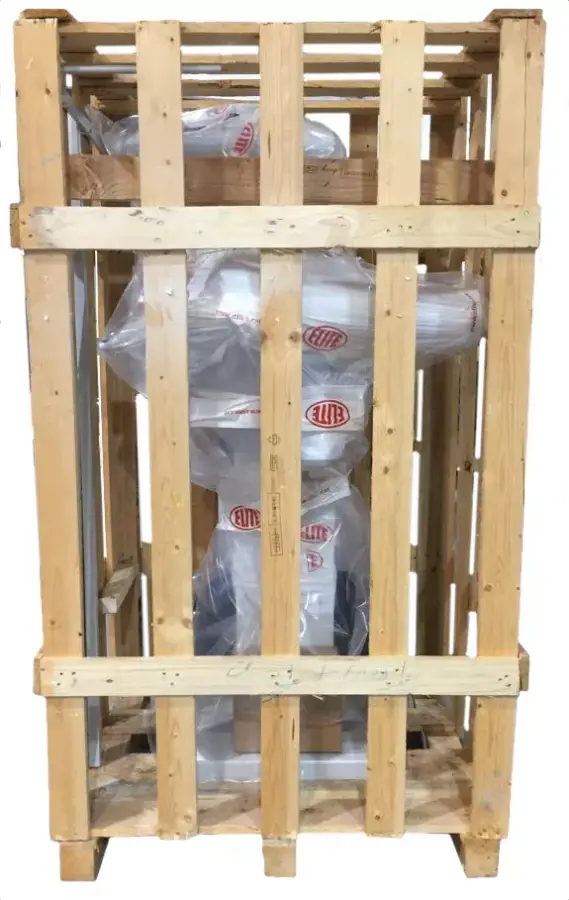
4.TRANSPORT
The SC 2 is delivered packed in a wooden crate.
During all transport and transfer, the machine must be kept in its original vertical position, any variation in this position may lead to the loss of the guarantee.
| Machine model | Dimensions (mm) | Weight (kg) |
|---|---|---|
| SC 2 | 980 x 810 x 1710 | 122 |
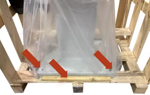
4.1.Instructions for unpacking and setting up
Take special care when lifting the load: The load may not be centered!
To lift or move the load, use a forklift with blades long enough to support the machine, taking into account the width and depth of the machine when calculating the weights to be lifted.
To unpack, first remove the front panel. Remove the wooden blocking pieces or the fixing screws on the feet of the machine.
Back side description
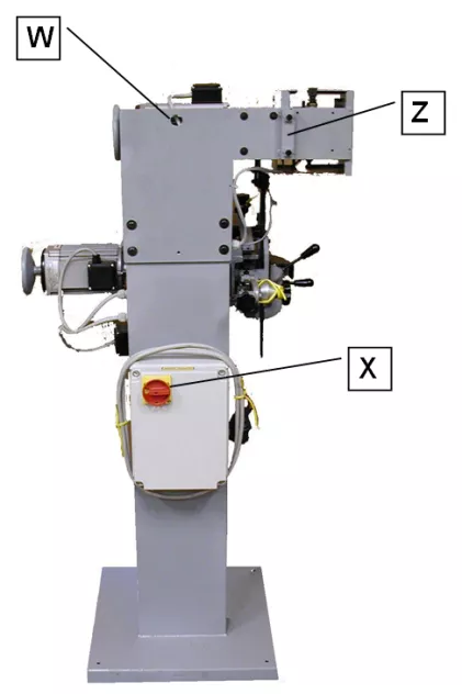
- W Ring for transporting the machine without packaging
- Z Height-adjustable rod holder for rolls
- X Main switch (yellow - red)
At the rear there is a ring (W) for transporting the machine. Once the machine has been transferred to its final work destination, you must fix the machine to the ground using the 4 screws placed on the base support of the machine. If this is not done, there is a high risk of the machine tipping over and causing serious injury to personnel and the machine itself.
Once the machine is in its final location, you can also remove the protective film and other protections from the components, which secure and prevent the machine from moving.
Insert the rod with the rolls in its vertical place (Z) on the back side of the machine. Move the rolls so that they can keep in place the ring of the blade during setting and sharpening operations. Block the lower end of the support using the bolts that you can find in the housing. Each roll is used for a specific operation.
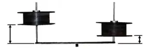
The roll for SETTING must be positioned 3-4 cm. from the horizontal rod. The roll for SHARPENING must be positioned 15-20 cm from the horizontal rod.
5.INSTALLATION
5.1.Machine placement
Before any work make sure that the machine is well aligned and does not oscillate at any of its ends, in which case it must be wedged to avoid movements. For its correct level it is necessary to use a leveling tool. This check must be carried out both longitudinally and transversally.

Poorly leveling the machine can cause unwanted vibrations and premature wear of the linear guides.
WARNING: The machine must not be used under any circumstances by unqualified or unauthorized personnel.
5.2.Electrical connection
DANGER HIGH VOLTAGE!
The electrical connection of the machine must be carried out by qualified technical personnel only at the voltage indicated in the machine order / machine identification plate.
For any doubt about the voltage, consult the manufacturer before the connection.
Any claim for an incorrect connection will be out of warranty.
The machine is equipped with plug CE and must be connected with a three-phase network** (380V): this is written on the label on the back side of the machine.
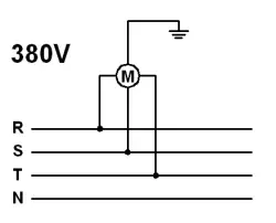
Only the earth cable can be connected with the yellow-green cable in the middle (earthing).
Note:
- The machine can work also with 220V three-phase. In this case you must modify the configuration of the clamp set. This change can be demanded at the moment of the order.
- On request, the machine can be prearranged for being connected with a single-phase network (220V).
We do not assume any responsability in case of a wrong electric connection that may cause not only a bad performance of the machine, but also damages to people, animals, things.
Remember: Before connecting the machine, remove any guards the machine may have to protect the components during transport.
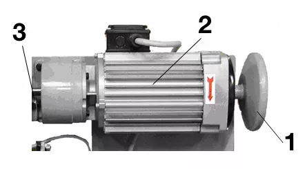
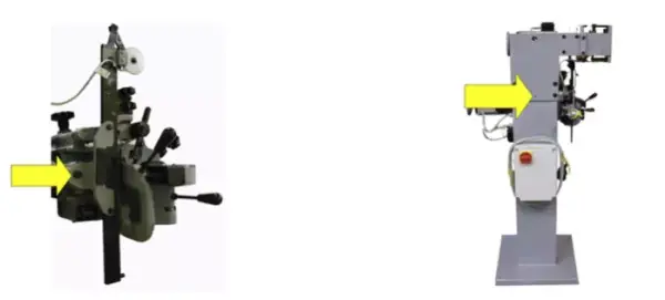
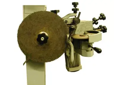
5.3.Main components of the machine
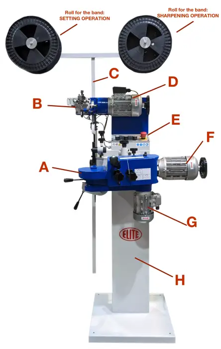
A. Grinder unit
B. Setter unit (optional)
C. Rod of rolls for bandsaw
D. Motor and reduction unit of setting machine (optional)
E. Control panel
F. Driving motor of grinder unit
G. Motor for grinding wheel rotation
H. Base
5.4.Control panel
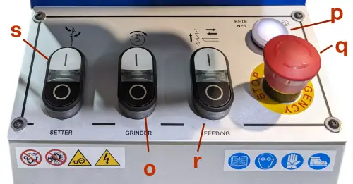
Buttons description:
- o: Button START / STOP grinding wheel rotation
- p: Power indication lamp
- q: Emergency STOP button
- r: Button START/ STOP feed of grinder unit
- s: Button START / STOP setter motor (optional)
6.STARTING UP
In this section we show you to operate the SC 2 in order to work.
Setting up video

Instruccions
NOTE: The data that appears in the different images are by way of example, each type of tool has its recommended data and a skilled operator must know them.
Rotate the main switch on the electrical switchboard located on the back side of the base: the lamp P placed on the switchboard will light up indicating that the machine is ready to be used.

Correct operation sequence:
- 1st. Operation: Setting
- 2nd Operation: Sharpening
6.1 Prearrangement for setting and set up for setting machine
Gear Motor Unit
- Handwheel for setting machine motion (by hand)
- Setting machine motor
- Reduction unit
Tooth pusher direction R
Setting machine
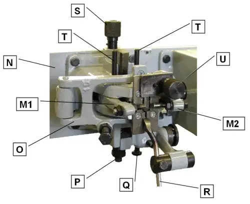
- M1. Adjustable hammer (left)
- M2. Adjustable hammer (right)
- N. Support for setter unit
- O. Support for band sliding with adjusting screw
- P. Adjusting screw for the vice closure (preregulated: DO NOT MODIFY)
- Q. Adjusting screw for the tooth pitch
- R. Tooth pusher
- S. Adjusting screw for amount of setting
- T. Little cylinders for manual opening of the vice
- U. Support plate that presses the band
6.1.1 Set up sequence
Pay attention when handling the blade during its installation: it is necessary to be very careful in order to avoid being hurt. It is necessary to wear work gloves to protect the operator from hurting himself with the teeth of the saw.
Hang the blade on the left roll with the back of the blade turned towards the back part of the machine, the teeth turned towards the front part and the cutters towards the floor.
The result of the following operations can be checked rotating by hand the handwheel, observing the motion of the setter.
Open the support plate that presses the band (U) used for pressing the blade. Rotate the handwheel (I) until the little hammers M1 and M2 reach the maximum opening.
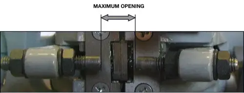
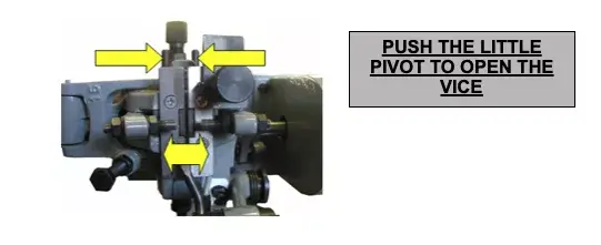
Open the jaws of the vice and press the two little cylinders T of the setting device, using your fingers.
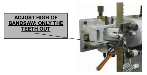
Adjust the height of the blade sliding support (screw O), so that only the tooth profile protrudes entirely from the jaws of the vice. Close the plate U on the teeth of the blade. Pressing the blade against the support, the plate guarantees a right operation. At the same time the blade can slide well.
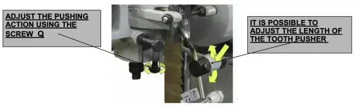
Position correctly the tooth pusher R. It must push only one tooth at a time.
IMPORTANT: The perfect pushing action of the tooth pusher is very important: the whole setting operation depends on it.
Adjust the blade feeding (adjusting screw Q) in conformity with the pitch of the teeth and the type of setting. The tips of the teeth must reach the same trajectory of the little hammers
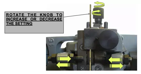
Adjust the quantity of setting using the adjusting screw (screw S) changing the race between the two little hammers (right and left) that move alternately but symmetrically, moving at the same speed. Increase or decrease the travel of the two little hammers (right and left) according to your needs. You can also modify the length of the little hammers M1 and M2 using the adjusting nut.
Rotate the handwheel I and observe the result that you have obtained. If you do not obtain a good result, repeat the operation changing values.
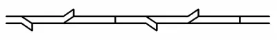
6.1.2 Type of setting
This setter can perform two types of setting:

The machine is always preset for type of setting.
To pass from type of setting A to type of setting B
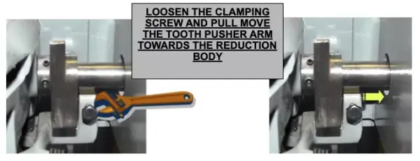
Looking at the setter from the front: on the right side there is a cam between the setter and the reduction gear. Loosen the clamping bolt of the bearing and move the tooth pusher arm towards the reduction body and screw the clamping screw.
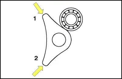
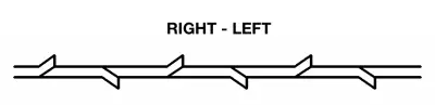
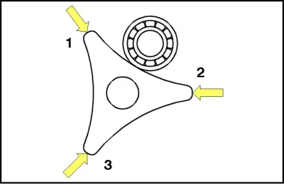
Result of this operation: the bearing that is on the tooth pusher arm moves on the portion of the cam having only two tips: the setting will turn into type B (teeth bended left/right).
Type B
Back to type of setting A
Starting from the cam between the setter and the reduction gear, loosen the clamping screw and press the tooth pusher arm towards the setter body.
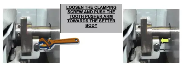
Result of this operation: the bearing that is on the tooth pusher arm moves on the portion of the cam having three tips: the setting will turn back into type A (teeth bended right/left/straight).
Type A
7. WORK OPERATION
7.1 Setting operation
The starting of the setter is possible only when the movable protective cover V in front of the moving parts is perfectly closed.
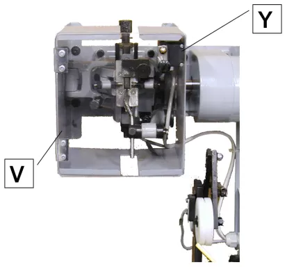
V: Movable protective cover
Y: Sensor

For stopping the machine automatically after a full turn, place a small magnet (supplied with each machine) on the edge of the band already set. The magnet will cause the shutdown near the sensor Y.
Make sure that the lamp p is lighted and the movable protective cover V is closed. Press the green button 1 (push-button panel) in order to start the setter.
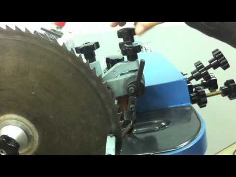
7.2 Sharpening: prearrangement and operation
Sharpener description
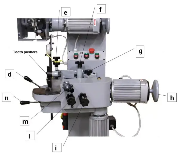
- d: Knob for opening the blade vice
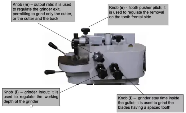
- e: Knob for regulating the tooth pusher feed
- f: Knob for tooth pitch variation
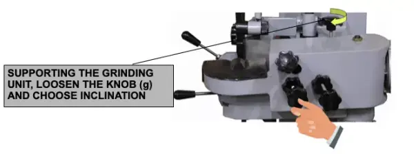
- g: Knob for regulating the grinder inclination
- h: Handwheel for grinder unit manual movement
- i:Knob for spaced tooth
- l: Knob in/out (depth of gullet)
- m: Knob for the grinder output rate (tooth back)
- n: Lever for the manual grinder unit shift
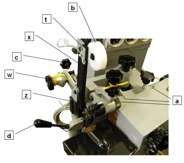
Description: blade guide unit and tooth pusher
- c: Knob for regulating the blade guide
- d: Knob for opening the vice
- z: Spacer for small size circular blades
- a: Oliers
- b: Device for pressing the blade
- w: Support for circular blades
- t: Sensor
- x: Blade guide
Set up sequence
For this operation the machine must be turned off:
Remove the ring of the toothed blade from the left roll (setting) and hang it on the right roll (sharpening). Keep the back of the blade turned towards the back side of the machine and the teeth turned towards the front part. Unlike the previous operation, the cutters must be turned upwards.
Open the blade guide using knob c and open the vice using lever d. Screw knob l in order to remove the grinder unit from the bandsaw.
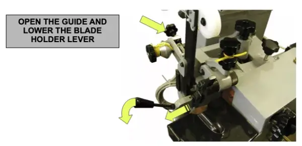
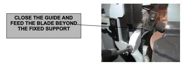
Insert the bandsaw in the blade guide and close the vice using lever d. Rotate the knob c in order to feed the bandsaw. The teeth gullet must protrude from the lateral fixed support of the vice (about 2 mm.).
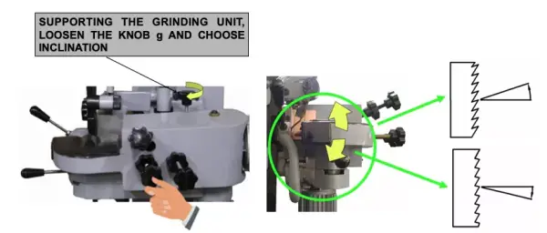
Using knob g unblock the grinder unit (attention: support by hand the whole unit) and regulate the inclination according to the cutting angle of the bandsaw.
Rotate the handwheel h: the tooth pusher causes the blade feed. Regulate it using the adjusting screw of the tooth pitch f.
Loosen the knob l: the grinder unit advances towards the blade cutter. check that the grinder does not strike the tooth. If the grinder strikes the tooth, go back to the previous point and regulate again the feed pitch, increasing it.
For this operation the machine must be turned on:
Push buttons r and o to start the feed and rotation motors of the grinder.
Regulate the grinder in/out run using knob l in order to sharpen the whole cutter until the bottom of the tooth gullet. Using the pitch adjusting screw e put the grinder in contact with the cutter (avoid an exaggerated removal).
Regulate the grinder exit using knob m. This operation regulates also the tooth back sharpening. Delaying the grinder exit, the grinder grinds the cutter back while the tooth pusher feeds it downwards.
Knob i must usually keep completely loosened. If you are using a blade with spaced teeth, use this knob for increasing the grinder stay time inside the gullet in order to grind also the straight portion of the gullet.

The sharpening operation is now set correctly and the machine can work automatically and non stop.
For stopping the machine automatically after a full turn, place a small magnet (supplied with each machine) on the edge of the band already set. The magnet will cause the shutdown near the sensor t.
IMPORTANT!
The tooth pusher must always push the tooth that it is sharpening. This is the most important rule to follow when using any type of sharpener.
A run which is too short does not permit the blade to advance, whereas a too long run causes a poor sharpening.
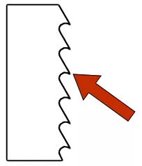
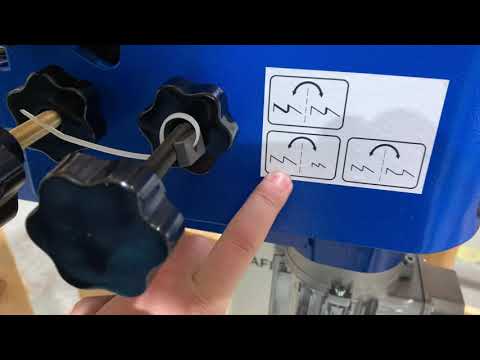
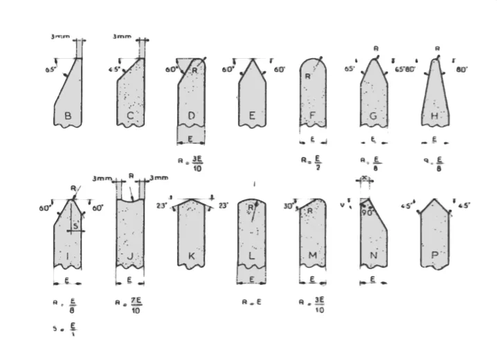
IMPORTANT!
Depending on the shape of the tooth that we want to obtain, we must give a previous shape to the grinding wheel as shown in the following information table:
7.3 Circular blades sharpening
To sharpen circular blades, it is necessary to shift the whole blade guide unit, putting it on the back side of the machine. Loosen the bolt and remove the unit. Screw it on the back side of the machine (threaded hole).
In case of blades having diameter <150 mm., use spacer z.
(Remove spacer z, loosen support unit w, connect spacer z on the right side of the guide turned towards the right side, then connect the support unit w to the spacer).
**ATTENTION!
- You can sharpen only circular blades without inserts and made of steel.
- The back side of the tooth must not be >20mm.**
For this operation the machine must be turned off:
Attach the saw blade on the appropriate w support. To continue sharpening the blade on the appropriate place w support group, unscrew the knob of said support and insert the blade between the two conical pressure. The group support w circular blade can slide along a guide to enable you to sharpen blades with different diameters. Once correctly positioned the blade close the w group knob.
Using knob g unblock the grinder unit (ATTENTION: support by hand the whole unit) and regulate the inclination according to the cutting angle of the bandsaw.
Rotate the handwheel h: the tooth pusher causes the blade feed. Regulate it using the adjusting screw of the tooth pitch f.
Loosen the knob l: the grinder unit advances towards the blade cutter. Check that the grinder does not strike the tooth. If the grinder strikes the tooth, go back to the previous point and regulate again the feed pitch, increasing it.
For this operation the machine must be turned on:
Push buttons r and o to start the feed and rotation motors of the grinder.
Regulate the grinder run using knob l in order to sharpen the whole cutter until the bottom of the tooth gullet. Using the pitch adjusting screw e put the grinder in contact with the cutter (avoid an exaggerated removal).
Regulate the grinder exit using knob m. This operation regulates also the tooth back sharpening. Delaying the grinder exit, the grinder grinds the cutter back while the tooth pusher feeds it downwards.
Knob i must usually keep completely loosened. If you are using a blade with spaced teeth, use this knob for increasing the grinder stay time inside the gullet in order to grind also the straight portion of the gullet.
The sharpening operation is now set correctly and the machine can work automatically and non stop.
For stopping the machine automatically after a full turn, place a small magnet (supplied with each machine) on the edge of the band already set. The magnet will cause the shutdown near the sensor t.
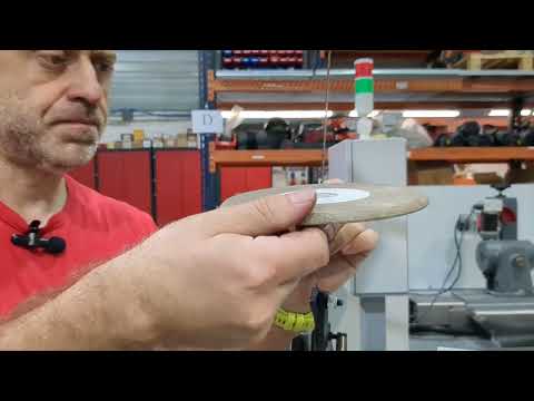
7.4 How to change the grinding wheel
8.MAINTENANCE
8.1.Preventive maintenance
The maintenance of the ELITE model SC 2 grinding machines is very simple but at the same time important.
It consists of the following:
- Cleaning of the carriage guides - Daily
- Cleaning and greasing the polished parts, in case the machine is not used for several days, to prevent oxidation.
- The dirty that is deposited in the work area must be emptied. NEVER USE COMPRESSED AIR it will move the dirty inside the guides and moving parts - Weekly.
- Keeping the machine clean and in good condition will allow for optimal long-term use.
Use the equipment only in dry environments. The temperature must be between 5 and 40ºC. A relative humidity greater than 90%, as well as a saline environment, would cause premature corrosion of the machine.
9.ACCESSORIES AND CONSUMABLES
9.1.Grinding wheels
The machine is equipped with a grinder type:
Abrasitec ref. 5211-A - Grinding wheel ø150X6xø20 mm.
To substitute the wheel, follow this procedure:
- Turn the machine off
- Push the emergency button (or disconnect the machine)
- Remove the grinder cover, using a key 20 loosen the bolt which is at the centre of thE grinder clockwise, then substitute it and tighten the bolt Counter-Clockwise
- Disconnect the emergency button (or connect the machine)
9.2.Equipment
Additional equipment of the machine.
9.2.1.Variable speed drive
Machine could be equipped with a variable speed to grind slowly for a better surface quality and easy setting up. The variable speed drive doesn't need any maintenance.
9.2.2.Setting device
The machine can be equipped with the setting device model ELITE TR 2 or ELITE TR 3
10.WARRANTY
All our machines are tested before being shipped. However, there can always be defects that are not observable at first sight.
Our machines are guaranteed against manufacturing or material defects under normal use and maintenance conditions.
The period of this guarantee is 12 months from the date of purchase and consists of the replacement of defective material.
The guarantee will be automatically canceled in the event of a modification outside our company. Or in manifest cases of misuse of the machine.
The guarantee does not include parts subject to normal wear due to use such as skids, lubrication cartridge, abrasives, etc.
11.PROBLEMS AND SOLUTIONS
In case of problems, read this section. Problems can be solved acting on different values:
* You cannot start the machine.
Solution: Check that the machine is correctly connected with the three-phase network. Check that the electric tension corresponds to the one indicated on the machine. Check that the motors turn in the direction indicated by the arrows, otherwise invert the position of the two wires on the current plug.
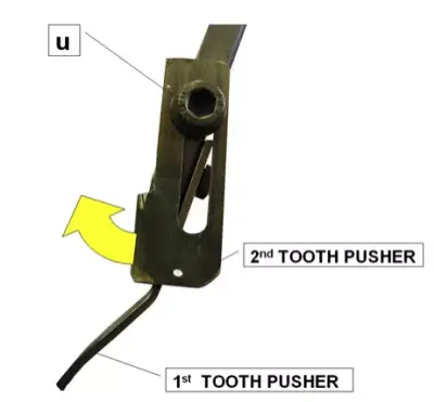
- The blade does not move.
Solution: Check the blade: it may have one tooth less. Regulating the second tooth pusher, you should solve this problem. For this operation: loosen screw u and regulate the second tooth pusher. Then close the screw u again.
- While sharpening, the machine aims to wear the tooth.
Solution 1: The setting pitch may not be regulated correctly. Using knobs g or e regulate the feed pitch of the band.
Solution 2: Knob i used to regulate the spaced pitch may be screwed. If you do not need a spacing between the teeth, this knob must be kept loosened.
Solution 3: The wheel may be too worn-out and may need to be replaced.
Solution 4: The blade may not be positioned correctly. Check that it is free to slide perfectly along its guide.
- The machine stops inexplicably.
Solution 1: It may be due to the magnet used for the automatic stop of sharpening operation. Check its position and, if necessary, position it correctly.
Solution 2: The protective cover v may be open or closed wrongly.
Solution 3: The emergency button q may have been activated: disable it.
Solution 4: There may be a motor overheating due to a prolonged use of the machine. Let motors rest for a while, then start the machine again.
- The setter vice does not operate correctly on the blade; you are using blades having a thickness >1 mm or < 0,6mm.
Solution: The setter vice is preset for blades having thickness between 0,6 and 1 mm. If your blades have a different thickness you must use screw p: increase or decrease the vice opening (ATTENTION: blade thickness MAX 1,2 mm).
For any other problem, get in touch with us: www.elite.es or [email protected]