1. FIRST STEPS
Congratulations on your purchase of the ELITE SOLDAmaq 1200 welding machine for carbide-tipped circular saw blades.
Read this guide before you start.
The ELITE SOLDAmaq 1200 is specially designed for welding and un-welding of the teeth on carbide tipped circular sawblades. For the repair of carbide-tipped circular saw blades
You can view the product catalog at the following link: ELITE model SOLDAmaq 1200
This manual introduces you to the main functions of the welder in order to avoid risks to your health or that may cause a breakdown or premature wear of the machine.
In case of any doubt, please contact us directly or one of our authorized distributors.
Informative Note: The use described in the manual of this welder may present some variations in use since our machinery is subject to possible constructive modifications, depending on the incorporation of technological advances in our welding equipment.
2. SECURITY
2.1.Safety rules
Carefully observe and apply the following safety rules, non-observance of these rules may cause personal injury or damage to the machine itself.
The installation and maintenance of the machine described in this manual must be carried out only by operators who are familiar with its operation and have sufficient technical knowledge.
The ELITE welding machine SOLDAmaq 1200 has been designed for the repairing of circular saws, excluding any other type of operation.
DANGER HIGH VOLTAGE

DANGER OF ACCIDENT

DANGER DUE TO SPARK PROJECTION

WEAR PROTECTIVE SHOES

DANGER FROM SHARP TOOLS

USE HEARING PROTECTORS
These warnings do not include all possible risks that improper use of the machine could cause. For this reason, the operator must proceed with prudence and observing the rules.
2.2.Use and storage of the instruction manual
This instruction manual must be read and understood by all personnel who come into contact with the machine.
This manual is for:
- Indicate the correct use of the machine according to the type of work to be carried out.
- Provide the necessary instructions for the transport, adjustment and maintenance of the machine.
- Facilitate the ordering of spare parts and information of risks.
Limits of use of the manual:
The machine is intended for professional use and therefore the experience of the operator is required and of vital importance.
Importance and conservation of the manual:
This manual must be considered part of the machine and must therefore be attached to it until the end of its use.
Additional information and clarifications:
The user, owner or maintenance person can contact the manufacturer to request any additional information on the use of the machine and possible modalities for maintenance and repair intervention.
Expiration of responsibility:
The manufacturer is considered exempt from any liability in the event of:
- Improper use of the machine
- Use of the machine by untrained persons
- Serious failures in scheduled maintenance
- Unauthorized interventions or modifications
- Use of non-original spare parts.
2.3.Declaration of conformity
The company hereby:
Elite Sharpening Machines, SLU
Joan Oró, 27
ES-08635 Sant Esteve Sesrovires
Declares that the product indicated below, based on its conception and construction, as well as the version put on the market by our company, complies with the mandatory basic health and safety requirements of the CE directive.
This declaration loses its validity in the event of unauthorized modifications to the product.
Product name: ELITE model SOLDAmaq 1200
Product type: Welding machine for carbide-tipped circular saw blades.
Serial No.: __
EC Directive Competences:
- EC Machinery Directive (2006/42/EC)
- European directive on electromagnetic compatibility (2014/30/EU)
- The protection purposes of the CE low voltage directive (2006/95/CE) were fulfilled according to annex I, nr. 1.5.1 of the machinery directive 2006/42/EC
The technical documentation was compiled by legal representative of the documentation:
Sergi Valls Gramunt
Joan Oró, 27
ES-08635 Sant Esteve Sesrovires
Date / manufacturer - Signature: __
Signatory data: Sergi Valls Gramunt, manager
3.TECHNICAL DATA
In the following information table, find the list of technical specifications of the welders described in this manual.
| TECHNICAL DATA | SOLDAmaq 1200 |
|---|---|
| Saw blade diameter | From 150 to 1200 mm (5.9" to 47") |
| Saw blade hole | From 20 to 130 mm (0.78" to 5,11") |
| Brazing angle | From -20 to +25º |
| Installed power | 4 kW |
| AVAILABLE VERSIONS | ||
|---|---|---|
| Model | Size | Weight |
| SOLDAmaq 1200 | 930 x 700 x 1300 mm. | 105 Kg. |
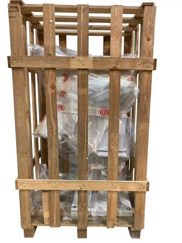
4. TRANSPORTATION
The ELITE SOLDAmaq 1200 is delivered packed in a wooden box.
During all transport and transfer, the machine must be kept in its original vertical position, any variation in this position may lead to the loss of the guarantee.
| Model | Packing Size | Gross weight |
|---|---|---|
| SOLDAmaq 1200 | 1000 x 800 x 1700 mm. | 135 Kg. |
4.1.Unpacking and assembly instructions
Take special care when lifting the load: The load may not be centered!
To lift or move the load, use a forklift with blades long enough to support the machine, taking into account the width and depth of the machine for the calculation of the weights to lift.
To unpack, first remove the front panel.
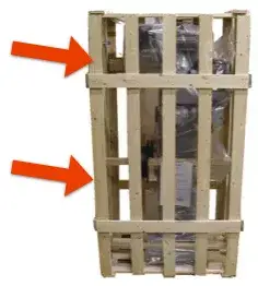
Remove the wooden blocking pieces or the fixing screws on the feet of the machine.
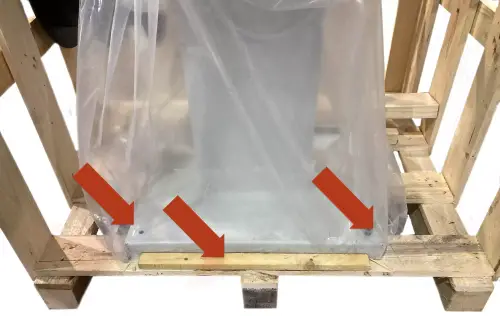
Once the machine is moved to its final working destination, you must fix the machine to the floor by means of the 4 screws placed in the machine base stand. If this is not done, there is a high risk to dump the machine and to cause serious injuries to the personnel and machine itself.
Once the machine is in its final location, you can also remove the protective film and other protections from the components, which secure and prevent the machine from moving.
5.INSTALLATION
5.1.Machine placement
Before any work, make sure that the machine is well aligned and does not oscillate at any of its ends, in which case it must be shod to prevent movement. For its correct leveling it is necessary to use a leveling tool. This control must be carried out both longitudinally and transversally.
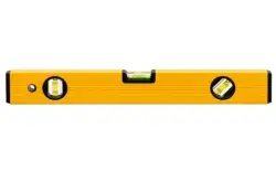
A poor leveling of the machine can cause unwanted vibrations and premature wear of the linear guides.
ATTENTION: The machine must not be used under any circumstances by unqualified or unauthorized personnel.
5.2.Electrical connection
DANGER HIGH VOLTAGE!
SOLDAmaq welding machines must be strictly connected to the voltage indicated in the machine order and on the machine itself. The connection to a voltage other than that indicated may cause a breakdown in the machine and represents a risk for people who use the machine.
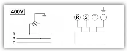
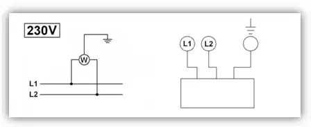
For its connection to the electrical network, the machine requires only two phases and the ground connection.
This installation must be carried out by qualified technical personnel and checked with a voltage meter before turning on the machine.
It is absolutely essential that the cross-section of the connection cable is as required, that the machine has a dedicated socket protected against overloads and that it is as close as possible to the socket.
In case of an inadequate section of the cable, not enough current will reach the machine at the time of welding, causing a defective and extremely fragile weld. This is one of the most important points since a very high number of possible welding problems is due to this problem.
Elite Sharpening Machines, rejects all responsibility for a wrong connection, which in addition to causing a malfunction of the machine can harm people, animals, material objects.
Remember: Before connecting the machine, remove any guards the machine may have to protect the components during transport.
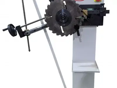
5.3.Main components of the machine
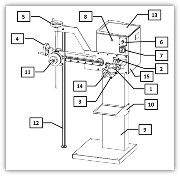
1 Crank to position and adjust the plate. 2 Crank to fix the plate. 3 Closing position adjustment screw 4 Handwheel for adjusting the diameter of the saw 5 Handwheel for adjusting the saw angle 6 Potentiometer for activation and adjustment of current intensity. 7 Main switch 8 Machine running indicator light 9 Machine base 10 Carbide pad collection tray 11 Saw holder 12 Saw holder reinforcement support 13 Upper tray 14 Jaw 15 Electrical panel
6.STARTING UP
In this section we show you how to operate the ELITE SOLDAmaq 1200 to make it work.
NOTE: The data that appears in the different images are by way of example, each type of tool has its recommended data and an expert operator should know them.
DANGER: never manipulate the buttons on the control panel while performing maintenance on the machine: danger of very serious injury. It is strongly recommended to switch off and disconnect the machine from the mains when working inside it.
6.1. Power on the machine
The SOLDAmaq 1200 welding machine has been designed for welding carbide-tipped circular saw blades with the maximum dimensions described above in the technical characteristics.
The machine is built from welded and machined parts.
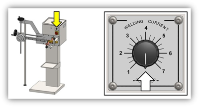
Once the machine has been connected to the network, it can be started up. First make sure that potentiometer 6 is disconnected.
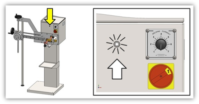
To start the welder, turn the main switch clockwise.
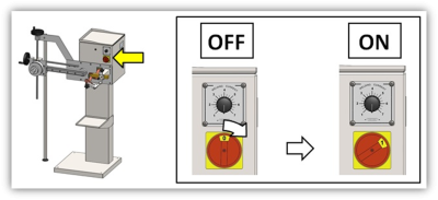
Make sure the machine is running by checking that the start light is on
6.2. Set up
7.WORK OPERATION
7.1.Weld adjustment
The machine heats the tooth using current until the flux used to bond the carbide plate to the body melts. Also for pre-welded tips (for example those coated with low melting point cast alloy) or triple metal alloy strip – to be placed between the carbide tip and the saw body – can be used.
Based on previous experiences, pre-welded plates are definitely the most practical.
7.1.1. Preparing the arm for plate welding

First, prepare to allow locating the body of the saw.
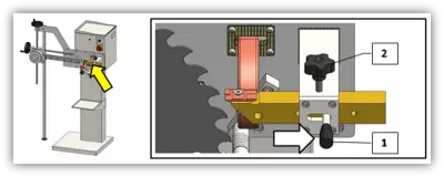
Rotate the cam to move the saw holder away from the position where the carbide plate is located.
Loosen cam 2 and move the plate support backwards using cam 1.
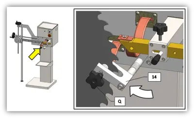
Turn lock 14 anti-clockwise so that it does not impede the insertion of the saw.
Once the machine has been adjusted, insert the saw to which we want to weld the carbide plate with the most suitable support.
7.1.2. Positioning the saw on the support
To position the tooth of the saw we have to proceed as follows. The type of clamping depends on the inner hole diameter of the blade being installed. For blades with a hole greater than Ø130 mm ask for special holders which do not come with the machine.
According to the type of holder to be used insert the suitable pivot in the carriage.
7.1.2.1 Blade with hole from Ø 20mm to Ø 55mm
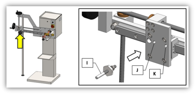
In these cases, use the small blade holder. Then, insert the suitable pivot I on the carriage unit. Two positions are possible, i.e. J and K. Choose position J for bigger blades (ØE >300mm) and position K for smaller ones (ØE <300mm). Screw the pivot and block using the nut.
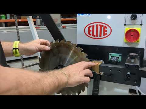
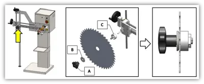
Unscrew the star knob A (Figure 9) of blade holder. Insert the circular blade into the blade holding unit between the two supports B and C and tighten star knob A. Insert the blade with the tooth tips oriented in anticlockwise direction. Then insert the unit into pivot I.
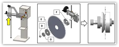
7.1.2.2 Blades with hole from Ø 55mm to Ø 130mm
In these cases use the big blade holder and insert the suitable pivot H into the carriage unit in position G.
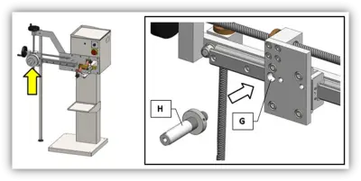
Remove safety plug D. Unscrew the blade holder ring nut O. Insert the circular blade into the blade holder between the two supports E and F and tighten ring nut O. Then insert the unit into pivot H and reinsert safety plug D. Insert the blade with the tooth tips oriented clockwise.
7.1.3 Adjustments
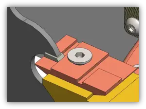
Adjust the blade position so as to bring the tooth closer to the insert rest. The tooth indentation aimed at hosting the insert shall be positioned so as to perfectly match the insert during the welding phase. To adjust the blade position, centre the blade with the tooth and adjust the blade angle proceed as follows.
7.1.3.1 Insert rest adjustment
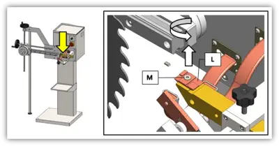
Insert rest L shall be arranged in a suitable position according to the dimensions of the insert to be welded to the blade.
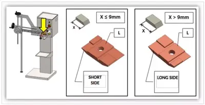
To free insert rest L and allow its positioning, remove screw M. Once the plate has been released, rotate it to the wished side. Then, reposition insert rest L and block it using screw M previously removed.
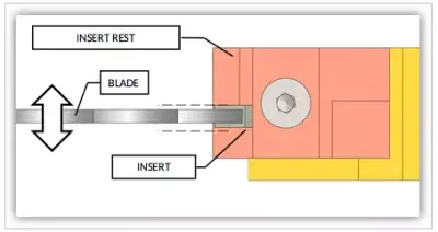
7.1.3.2. Blade position adjustment
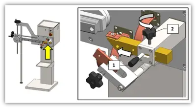
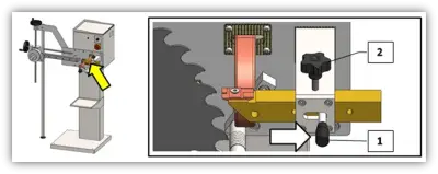
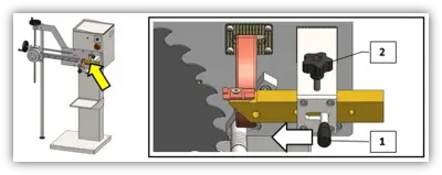
To adjust the blade position in relation to the insert rest, first move the insert rest to point where the insert will be welded. To this end, loosen locking star knob 2 and move the insert rest using knob 1 as indicated by the arrow in the following figure. Then relock the rest using star knob 2.
Now position one of the inserts to be welded to the blade on the insert rest as indicated in the followig figure. Always align the inserts with the rest sides (following figure) so that the welding position is always the same. The insert shall be oriented on the rest in the same direction as the one it shall have once welded to the blade.

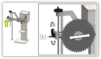
Adjust the blade position in relation to the insert rest using hand wheel 4 . Turn hand wheel 4 clockwise to move the blade away from the insert rest and turn it in an anticlockwise direction to bring it closer. Adjust the blade position so that the indentation on the blade tooth is in the proximity of the insert on the rest.
Adjust the blade position so that the proper indentation on the blade tooth is in the proximity of the insert located on the rest.
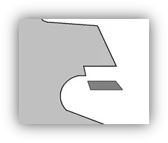
Once adjustments have been made the tooth indentation on the blade aimed at hosting the insert shall match the insert as indicated in the following figure. Now you just have to centre the blade with the insert.
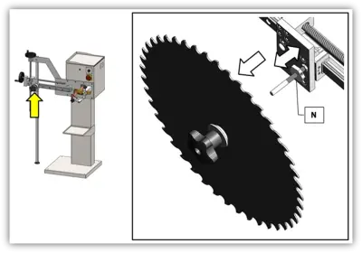
7.1.3.3. Blade insert centring
Once the blade has been positioned, centre it in relation to the insert.
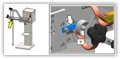
To centre the blade in relation to the insert use ring nut N of the small blade holder. To this end, remove the blade holder together with the blade and adjust the ring nut so that, once the holder back to its place, the blade will be perfectly centred in relation to the insert.
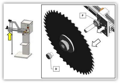
On the contrary, to adjust the big blade holder use ring nut P. First, remove safety plug D to allow the removal of the blade holder and the blade together. Adjust the ring nut so that, once the holder back to its place, the blade will be perfectly centred in relation to the insert.
7.1.4 Clamp positioning and adjustment
7.1.4.1. Clamp positioning
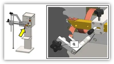
Loosen star knob Q of clamp 14 to allow the blade to enter the clamp cavity. Then turn clamp 14 as shown in the following picture.
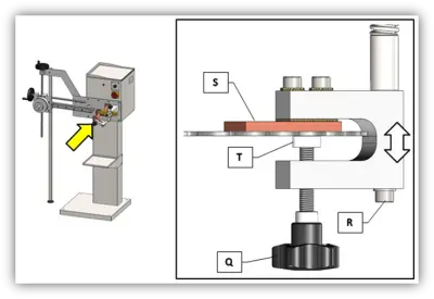
7.1.4.2. Clamp adjustment
Once the clamp has been positioned, you may proceed to its adjustment. Put copper plate S against the blade surface by means of screw R. To lock the blade in the clamp simply tighten star knob Q so that the nylon plug T is pressed against the blade. Position the clam so as to allow the blade to rotate freely once star knob Q is loose.
7.1.5 Use of the extension for small blades
If blades to be welded are very small, you need to use extension Q which is to be assembled to the carriage as shown in the picture on the left.
7.1.6 Blade preparation
If the blade on which the inserts are to be welded is not new but has to be repaired, before welding the inserts file the indentation on the blade tooth to remove any residues from previous welds.
7.2 Insert welding
Once the machine has been adjusted as indicated in section 7.1 you may proceed to the insert welding.
Once adjustments have been made the tooth indentation on the blade aimed at hosting the insert shall match the insert.
To weld the inserts proceed as indicated below.
-
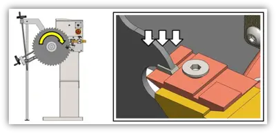
After loosening star knob 2 push the insert rest away from the blade using knob 1. Then lock using star knob 2.
-
Position the insert to be welded to the blade on the insert rest. Always align the inserts with the plate sides (indicated by the arrows in the following figure) so that the welding position is always the same.
The insert shall be oriented on the rest in the same direction as the one it shall have once welded to the blade.
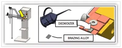
-
If you are using pre-welded inserts go to point 4. Otherwise, you will have to apply a drop of deoxidizer and a layer of brazing alloy (this alloy is usually sold in sheet form, having the same dimensions as the inserts to be welded).
-
Rotate the blade to make the tooth on which the insert is to be welded lie on the insert rest.
-
After loosening star knob 2 push the insert rest towards the blade by means of knob 1 . Then lock using star knob 2.

-
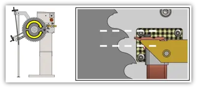
Now turn the blade clockwise to make the indentation on the blade tooth and the insert on the rest match. Once the tooth and the insert are in contact with each other keep the blade turned against the insert.
-
Tighten the clamp using star knob Q

-
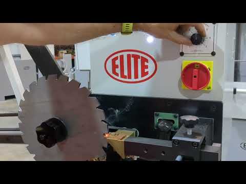
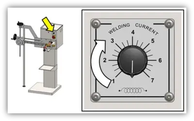
Keep the blade tooth well pressed against the insert and gradually turn potentiometer 6 to the suitable welding current (see Table 1 Chapter 9).
When the welding alloy melts this means the insert has been welded. Now turn potentiometer 6 back to zero. You can now proceed to weld other teeth.
7.3. Removal of damaged inserts
Once the machine has been adjusted as indicated in section 7.1, you may proceed to the removal of damaged inserts.
-
After loosening star knob 2 push the insert rest away from the blade using knob 1. Then lock using star knob 2.
-
Rotate the blade to make the tooth from which the insert is to be removed lie on the insert rest.
-
After loosening star knob 2 push the insert rest towards the blade using knob 1. Then lock using star knob 2.
-
Now turn the blade clockwise so as to push the insert against the rest. Once the tooth and the insert are in contact with each other keep the blade turned against the insert rest.
-
Tighten the clamp using star knob Q
-
Keep the blade tooth well pressed against the insert on the rest and gradually turn potentiometer 6.
When the welding alloy melts hit the insert with a blunt instrument to detach it from the tooth. Now turn potentiometer 6 to the off position (position indicator downwards). You can now proceed to the removal of other inserts, if necessary.
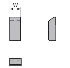
7.4. Table of operating characteristics
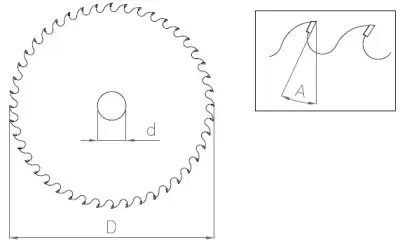
| Inner diameter d (mm) | Outer diameter D (mm) | Brazing angle A (º) | Tooth width W (mm) |
|---|---|---|---|
| From Ø20 to ø130 mm. | From ø150 to ø1200 mm. | From -20º to +25º | From 2 to 6 mm. |
7.5. Technical assistance service
At ELITE we try to satisfy our customers through reliable and easy-to-use products. However, if you experience any incident )while using the machine, do not hesitate to contact us as soon as possible directly or through our authorized distributors, who will assist you, if available in your country, with better proximity and professionalism.
We wish you to enjoy this product for many years, please: when the useful life of the soldering iron ends, dispose of it correctly to the necessary organisms for its correct disposal and recycling.
8.MAINTENANCE
8.1.Preventive maintenance
Maintenance of the SOLDAmaq 1200 welders is very simple. It consists of the following:
Clean the electrodes each time after welding, either with compressed air or with a cloth. They should only pass it lightly, without any cleaning additive.
This will greatly extend the life of the electrodes due to wear due to friction with the remains of the weld.
Verify that the welding input voltage is correct and does not present oscillations.
In case of damage, replace the damaged parts with new ones.
| PERIODIC CHECKS | ||
|---|---|---|
| TYPE OF CHECK | ACTION | WHEN |
| Insert rest cleaning | Carefully clean the insert rest surfaces using a rough cloth or an abrasive sponge | Before each welding |
| Contact cleaning | Periodically clean electrical contacts (terminal, braids, etc.) | When the contact surface is particularly filthy |
| Insert rest replacement | After long periods of use replace the insert rest | After a number of weldings |
Use the equipment only in dry environments. The temperature must be between 5 and 40ºC. A relative humidity greater than 90%, as well as a saline environment, would cause premature corrosion of the machine.
8.2. Problems and solutions
Problem: the machine does not switch on
Cause:
- Line voltage absent. Solution: check the connection
- Disconnecting switch failure. Solution: check the disconnecting switch connection. Check the disconnecting switch operation
Problem: the insert weld does not hold
Cause:
- The insert rest is filthy. Solution: clean and/or replace the insert rest
- Wrong welding parameters: Solution: chech parameters
Problem: Electric current does not get to the tooth during the welding
Cause:
- Clam Q is not correctly closed. Solution: check parameters (see section 7.2)
- Electrical contact are filthy: Solution: clean electrical contacts
- Pressure exerted on the insert during the welding is not enough. Solution: increase pressure during welding (see section 7.2)
9.ACCESSORIES AND CONSUMABLES
9.1.SOLDAmaq 1200 insert
10.WARRANTY
All our machines are tested before being shipped. However, there can always be defects that are not observable at first sight.
Our machines are guaranteed against manufacturing or material defects under normal use and maintenance conditions.
The period of this guarantee is 12 months from the date of purchase and consists of the replacement of defective material.
The guarantee will be automatically canceled in the event of a modification outside our company. Or in manifest cases of misuse of the machine.
The guarantee does not include parts subject to normal wear due to use such as skids, lubrication cartridge, abrasives, etc.
11.DOWNLOAD MANUAL
12.FAQ
Question nr1
Answer no. 1