1. FIRST STEPS
Congratulations on purchasing the ELITE 92 universal tool sharpener.
Please read this guide before starting.
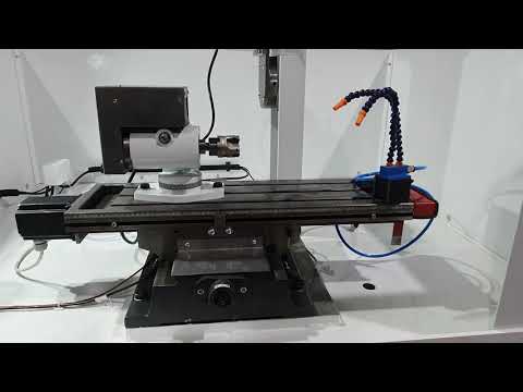
The ELITE 92 is our most popular universal tool sharpener due to its excellent price/performance ratio. It is specifically designed for sharpening tools in the woodworking sector. Its worktable allows a maximum load of 100 kg for the most common sharpening or grinding of cutting tools.
The X (cross) and Y (depth) axes move using ball linear bearings on hardened and ground steel guides. The movement of the Z (vertical) axis of the table is carried out using recirculating ball linear bearings. The X and Y axes are driven by ball screws, while the Z axis is driven by a trapezoidal screw.
This manual introduces you to the main functions of the sharpener in order to avoid health risks or damage and premature wear to the machine.
You can view the product catalog at the following link: ELITE 92
If you have any questions, please contact us directly or reach out to one of our authorized distributors.
Informative Note: The user manual of the universal tool sharpener described herein may present some usage variations, as our machinery is subject to possible construction modifications depending on the incorporation of technological advancements in our sharpening equipment
2.SAFETY
2.1.Safety regulations
Please observe and apply the following safety regulations carefully. Failure to comply with these regulations may result in personal injury or damage to the machine itself.
The installation and maintenance of the machine described in this manual must only be carried out by operators who are familiar with its operation and have sufficient technical knowledge.
The ELITE 70 sharpening machine has been designed for sharpening milling cutters and cutting tools, excluding any other type of operation.
DANGER HIGH VOLTAGE

DANGER OF ACCIDENT

DANGER DUE TO SPARK PROJECTION

WEAR PROTECTIVE SHOES

DANGER FROM SHARP TOOLS

USE HEARING PROTECTORS
These warnings do not include all possible risks that improper use of the machine could cause. For this reason, the operator must proceed with prudence and observing the rules.
2.2.Use and storage of the instruction manual
This instruction manual must be read and understood by all personnel who come into contact with the machine.
This manual is for:
- Indicate the correct use of the machine according to the type of work to be carried out.
- Provide the necessary instructions for the transport, adjustment and maintenance of the machine.
- Facilitate the ordering of spare parts and information on risks.
Limits of use of the manual:
The machine is intended for professional use and therefore the experience of the operator is required and of vital importance.
Importance and conservation of the manual:
This manual must be considered part of the machine and must therefore be attached to it until the end of its use.
Additional information and clarifications:
The user, owner or maintenance person can contact the manufacturer to request any additional information on the use of the machine and possible modalities for maintenance and repair intervention.
Expiration of responsibility:
The manufacturer is considered exempt from any liability in the event of:
- Improper use of the machine
- Use of the machine by untrained persons
- Serious failures in scheduled maintenance
- Unauthorized interventions or modifications
- Use of non-original spare parts.
2.3.Declaration of conformity
The company hereby:
Elite Machines, SLU
Joan Oró, 27
ES-08635 Sant Esteve Sesrovires
declares that the product indicated below, based on its conception and construction, as well as the version put on the market by our company, complies with the mandatory basic health and safety requirements of the CE directive.
This declaration loses its validity in the event of unauthorized modifications to the product.
Product name: ELITE 92
Product type: Universal tools sharpening machine
Serial No.: __
EC Directive Competences:
- EC Machinery Directive (2006/42/EC)
- European directive on electromagnetic compatibility (2014/30/EU)
- The protection purposes of the CE low voltage directive (2006/95/CE) were fulfilled according to annex I, nr. 1.5.1 of the machinery directive 2006/42/EC
The technical documentation was compiled by Legal representative of the documentation:
Sergi Valls Gramunt
Joan Oró, 27
ES-08635 Sant Esteve Sesrovires
Date / manufacturer - Signature: __
Signatory data: Sergi Valls Gramunt, manager
3.TECHNICAL DATA
In the following information table, find the list of technical specifications of the machine described in this manual.
| TECHNICAL DATA | ELITE 92 |
|---|---|
| Grinding wheel motor power | From 2000 to 4000 RPM and 1.5 HP (Optional up to 18000 RPM) |
| Grinding wheel diameter | Up to ø150 mm. |
| Working table dimensions | 800 x 160 mm |
| X- axis useful travel | 420 mm. |
| Y- axis useful travel | 200 mm. |
| Z- axis useful travel | 320 mm. |
| Vertical spindle rotation | 360º |
| Spindle horizontal rotation | 90º |
| Maximum weight on the table | 100 kg. |
| AVAILABLE VERSIONS | ||
|---|---|---|
| Model | Packing Size | Weight |
| Manual version | 1420 x 1100 x 1760 mm | 400 Kg. |
4. TRANSPORT
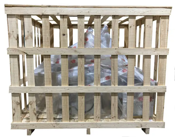
The ELITE 92 is delivered packaged in a wooden crate.
During all transportation and handling, the machine must remain in its original upright position. Any deviation from this position may result in the loss of warranty.
| Model | Packing Size | Weight |
|---|---|---|
| Manual version | 1420 x 1100 x 1760 mm | 400 Kg. |
4.1. Instructions for unpacking and setting up
The ELITE 92 grinder leaves our facilities properly prepared so that its mechanisms do not suffer any damage during transport. For this reason, and to put it into operational condition, it requires some procedures detailed below:
The machine must be moved to its installation site without removing any of the protective arrangements prepared for its transport.
When choosing the location for the machine, ensure that the floor is solid and free of vibrations.
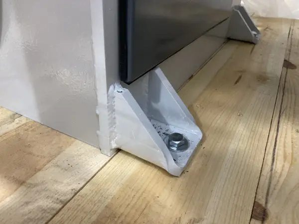
Once placed in the room, you can carefully remove the packaging. Remove the locking stops from the machine’s feet.
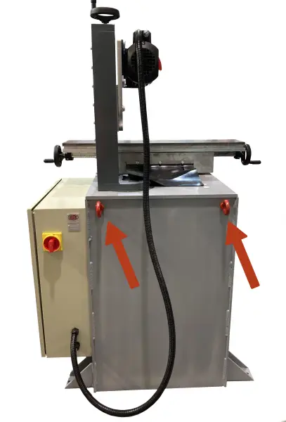
Use slings that can easily support the machine's weight to move it. On the front and rear of the machine, you will find holes to attach the slings.
Also, remove the anti-corrosion protective grease and lubricate the machine using lubricating oil. Failing to do so will make the movements rougher.
5.INSTALLATION
5.1.Machine Placement
Before any work, we must ensure that the machine is properly aligned and does not wobble at any of its ends; if it does, it must be shimmed to prevent movement. To achieve correct leveling, a spirit level must be used. This check should be carried out both longitudinally and transversely.

Level the machine using the supplied foot screws. Improper leveling of the machine can cause unwanted vibrations and premature wear of the linear guides.
Unlock the different movements and clean off the protective fluid coating some parts.
WARNING: The machine must never be operated by unqualified or unauthorized personnel.
5.2.Electrical Connection
DANGER HIGH VOLTAGE!
Remember: before connecting the machine, remove any protective covers that may be in place to protect components during transport.
The machine’s electrical connection must be carried out only by qualified technical personnel and strictly at the voltage specified in the machine order.
Verify that the voltage indicated on the machine matches the supply voltage.
For any doubts regarding voltage, consult the manufacturer before making the connection.
Any claims resulting from incorrect connection will void the warranty.
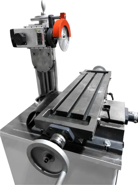
5.3.Main Components of the Machine
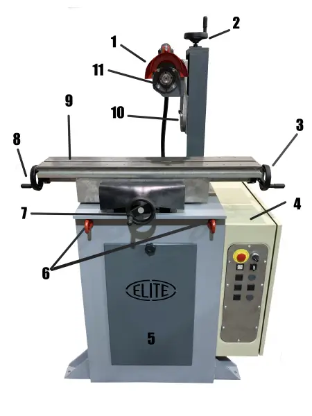
- Grinding wheel guard.
- Vertical movement handwheel.
- Longitudinal movement handwheel.
- Electrical panel.
- Accessory storage door.
- Lifting eyes for transporting the machine.
- Front movement handwheel.
- Longitudinal movement handwheel.
- Worktable.
- Grinding wheel angle adjustment on the vertical column plane.
- Grinding wheel / wheel holder.
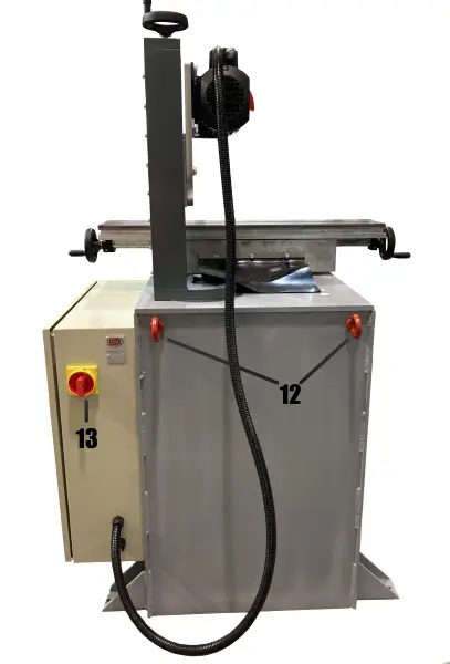
- ON/OFF switch
13.Lifting eyes for transporting the machine
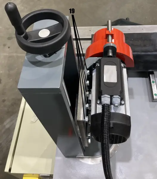
19.Screws for adjusting the motor position
5.4.Control panel
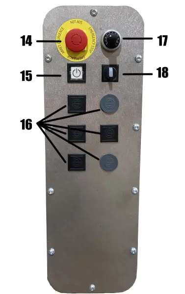
14.Emergency stop
15.Machine reset
16.Optional buttons
17.Wheel rotation speed selector
18.Wheel rotation direction selector
6.START-UP

Once the machine is positioned at its workplace, you must remove the protections installed for transport as well as the anti-corrosion protective grease.
If a cooling system is included, it must be filled with water + cutting fluid in the proper ratio according to the cutting fluid manufacturer and the water hardness. The water used must be potable, with a recommended hardness between 5º and 10º.
For electrical connection, you must contact a qualified technician according to the applicable regulations in your country.
Verify the motor rotation direction
To check the correct connection of the electrical phases, run the cooling pump motor and observe the rotation direction of the shaft; it must match the direction indicated on the pump. If it does not match, swap two of the phases at the machine’s connection input or at the electrical supply point.
The machine’s movements are locked for transport. It is important that once the machine is unpacked and placed in position, you unlock the movements to be able to use it.
Additionally, the anti-corrosion protective grease must be removed, and the machine lubricated using machine oil. Failure to perform this action will result in rougher movements.
6.1. Machine Start-Up
This section explains how the control panel buttons of the ELITE 92 operate.
NOTE: The data shown in the images are examples; each type of tool has its recommended settings, which the sharpening professional must know.
Emergency stop
This is the red button located at the lower right, on the second-to-last row of buttons. In case of any malfunction or if a dangerous situation arises, it allows the machine to be automatically shut off.
It should only be used when strictly necessary
Once used, to resume operation, pull the button back to its initial position and reset the machine.
WARNING: Under no circumstances should this control be modified or tampered with, as this immediately creates a serious risk of injury to the operator and people nearby.
Sharpening Operation
Before starting the sharpening process, make sure that the emergency stop button is not activated
The two types of modes it can operate in are STOP MODE and START MODE.
DANGER: Never operate the control panel buttons while changing the grinding wheel: risk of severe injury
WARNING: Before starting the wheel, ensure it is securely mounted on the spindle and that NO ONE is handling the area where it rotates. UNDER NO CIRCUMSTANCES should the wheel be started while someone is handling it.
6.2.Power On and Referencing
On the machine with a CNC control panel, after powering on, you will be prompted to reference the automated axes.
To do this, ensure the machine can move freely without colliding with any object or person. Then press the START button to confirm the referencing process.
Once the machine completes the process, it will remain stationary in the final referenced position of the axes and will be ready for normal operation
Referencing of axes and manual movement.
6.3.Grinding Wheel Guard
Always use the grinding wheel guard appropriate for the diameter of the wheel being used. Never exceed the maximum rotation speed recommended by the wheel manufacturer
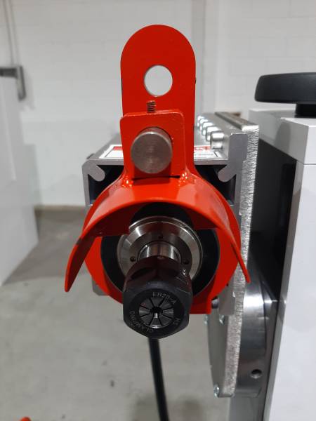
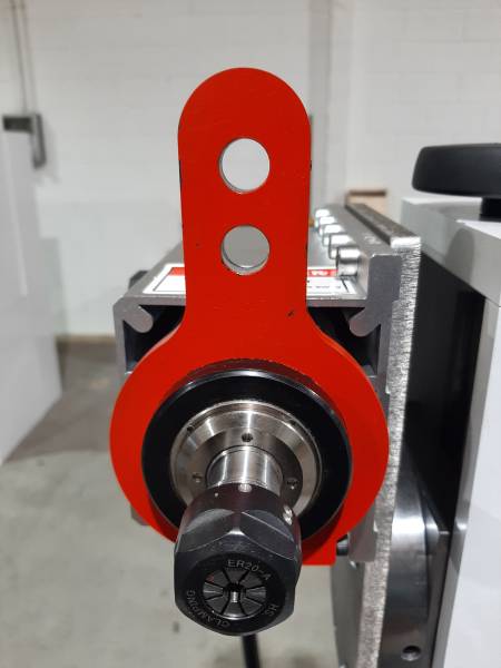
6.4.Installation of the Abrasive Pivot (Optional Accessory Available with the 18,000 RPM High-Speed Motor)
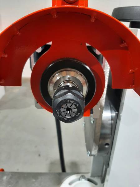
To install abrasive pivots, you must use the collet and collet holder supplied optionally. The standard collet diameter is ø6 mm. Other sizes up to ø12 mm are available as an option.
For mounting the abrasive pivot, you must also use the pivot guard. To do this, place the pivot guard’s holding shaft in the lower of the two available holes, as shown in the following image.
6.5.Grinding Wheel Head
Two types of grinding wheel motors are available:
1.5 HP grinding wheel motor with a rotation speed of 2,000 to 4,000 RPM, capable of rotating both clockwise and counterclockwise.
Direct-drive precision grinding wheel motor with variable speed from 3,000 to 18,000 RPM and 1.5 HP.
6.6.Movement of the Grinding Wheel Head Axis
The grinding wheel head can rotate 180° around its vertical axis and 360° around its horizontal axis.
6.7.Front Movement
This can be operated using the handwheel located on the front left. Its operation is manual, with a gear ratio sufficient to allow movement with maximum sensitivity.
6.8.Longitudinal Movement
The sensitivity of the longitudinal movement is of vital importance for the sharpening operation, as it allows detecting even the slightest pressure between the tool and the grinding wheel through touch.
For this reason, the sliding table is mounted on recirculating ball guides over linear guides made of hardened and ground steel, which allow smooth operation and ensure an even distribution of the table's weight.
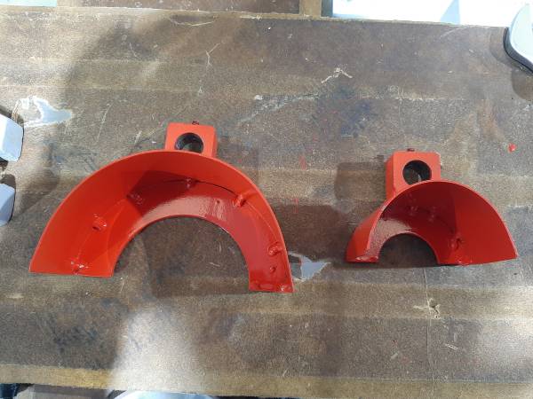
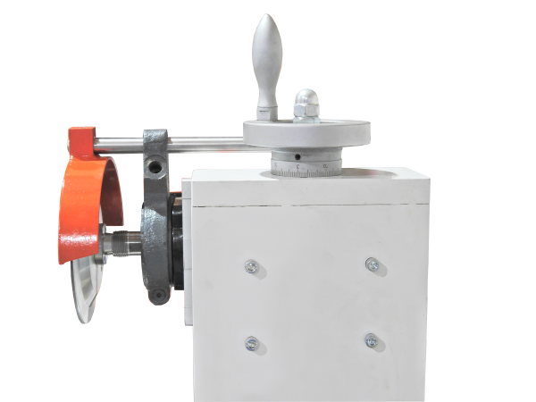
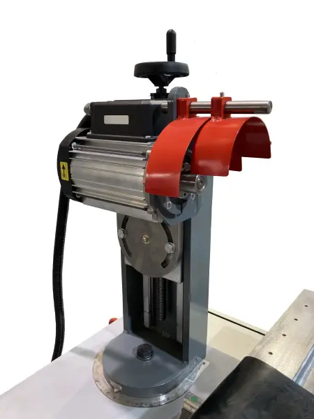
6.9.Safety
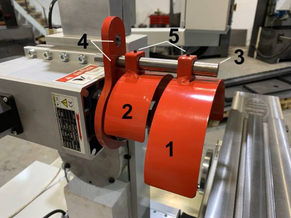
When using the machine, a sharpening wheel guard must always be used.
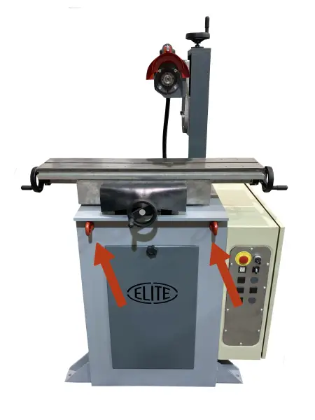
Two wheel holders are included depending on the diameter of the wheel to be used (Figures Nr. 1 and 2).
To do this, remove the wheel holder you are not going to use by loosening the screw shown in Figure Nr. 5.
To use the wheel holder shown in Figure Nr. 2, the height of the fixing bar (Figure Nr. 3) must be in the lowest position (Figure Nr. 4). To use the larger wheel holder, it must be in the highest position.
7.SHARPENING OPERATION
7.1. Wheel Holder and Vertical Movement
Precision direct-drive wheel motor with variable speed from 2,000 to 4,000 RPM and 1.5 HP. (Optionally available up to 18,000 RPM).
The vertical movement of the wheel is carried out using the top handwheel in the case of the manual machine.
If the sharpener is a CNC version and this axis is automated, the movement will be controlled from the control panel using the corresponding arrows.
7.2. Rotation Movement of the Wheel Head
The wheel head can rotate 180º around its vertical axis and 360º around the horizontal axis.

7.3. Front Movement
This can be operated using the central handwheel at the front of the machine; its operation is manual.
If the grinder is the CNC version and this axis is automated, the movement will be controlled from the control panel using the corresponding arrows.

7.4. Longitudinal Movement
This is performed using the handwheels located on the left and right sides at the front of the machine.
If the grinder is the CNC version and this axis is automated, or if the chosen option includes a motorized table movement, the motion will be controlled from the control panel using the corresponding arrows.
7.5. Optional Equipment
The Elite 92 grinder can optionally be equipped with a cooling system consisting of:
- 15 L tank for collection and storage of coolant.
- Pump
- Tubes and nozzle with adjustable valve
- Tray for collecting the coolant
For cooling, we recommend using Sintocut PRO MIX cutting fluid at a 3–5% concentration.
Additionally, the machine can also be optionally equipped with a chip extraction system to remove the shavings generated during sharpening.
7.6. Adjustments
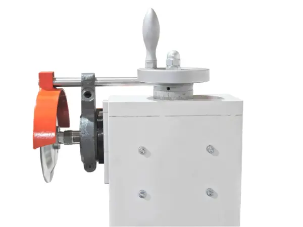
7.6.1. Head Travel
The sharpening head is fixed on the vertical column of the machine and can rotate in both horizontal and vertical planes.
The handwheel on the upper column moves the abrasive wheel upward or downward. Each full turn of the handwheel corresponds to a 4 mm movement.
The sharpening head can be tilted in the horizontal and/or vertical plane by loosening two bolts.
ATTENTION: TAKE SPECIAL CARE TO HOLD THE SHARPENING HEAD WHEN IT MOVES IN THE VERTICAL PLANE!!!
The safety cover can also rotate 360º via the fixing screw at the top of the cover.
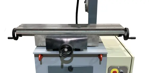
7.6.2. Worktable
The worktable has two T-slots, 14 mm wide, where any type of accessory can be securely mounted in the desired position.
The table is moved using the front handwheels.
7.7. Operation
The type of application or work that can be performed with the ELITE 92 universal grinder will vary depending on the accessories or optional equipment with which the machine was configured at the time of order, as well as the specific work the client intends to perform.
The ELITE 92 grinder can carry out the following tasks, always depending on the accessories with which it is equipped. These accessories are optional equipment that can be added to the base machine. Some examples of applications include:
- Sharpening cylindrical cutters
- Sharpening single-angle cutters
- Sharpening T-slot cutters
- Sharpening three-cutters
- Sharpening face mills
- Sharpening knives
- Sharpening carving tools
- Sharpening threading dies
- Sharpening drills
- Sharpening lathe tools
- Sharpening reamers
- Sharpening master gear cutters
- Sharpening pinion cutter
- Sharpening tools for point-to-point work (spindles, etc.)
- Flat surface grinding
8. MAINTENANCE
8.1. Preventive maintenance
WARNING: Do not clean or perform maintenance on the machine while it is connected to the power supply:
This can damage both the machine and the operator. Turn off the machine and disconnect it from the power source before performing any maintenance or cleaning tasks
The machine is low-maintenance and contains only a few parts that require servicing.
Any malfunction or defect that could compromise the safety of the machine must be addressed immediately.
- Repair activities can only be carried out by qualified personnel.
- Thorough cleaning ensures a long machine life and is a safety requirement.
- The use of solvents, aggressive chemicals, or abrasive cleaning products may damage the machine casing. Use only mild detergents for cleaning.
- Apply a light layer of anti-corrosive (e.g., WD40) to unpainted surfaces of the machine.
- After each work shift, clean the machine and all its parts thoroughly of dust and chips using a vacuum cleaner. Do not use compressed air for cleaning, as it can force particles into the guides and bearings.
- Regularly check that all warnings and safety instructions are present on the machine and fully legible.
- Before each use, check the condition of safety devices.
- Operate the equipment only in dry environments. Temperature should be between 5°C and 40°C. Relative humidity above 90% or a saline environment can cause premature corrosion of the machine.
8.1.1. Machine lubrication
After using the machine, it is recommended to clean and lubricate it to prevent rust and accumulation of dirt. Never use compressed air to clean the machine, as this action will embed dirt into the bearings and other moving parts of the machine
9.ACCESSORIES AND CONSUMABLES
9.1.Abrasive wheels
9.1.1.Sharpening cutters
For the sharpening of strawberries we recommend the following reference: 2141-A. 4A2. ø150x4x2x12xø20 mm.
For sharpening carbide burs with a narrow pitch we recommend the following reference: 2150-A. D76 C125. ø150x13x2.9x13xø32 mm.
9.2.Cooling agents
9.2.1.Work only with steel and HSS
We recommend using ELITE SintoCut MIX or equivalent when working only with steel.
9.2.2.Working with steel and carbide
If the machine is to work with steel and also with tungsten carbide, then it is better to work with SintoCut PRO MIX or equivalent, which is a better choice for working with carbide.
9.3.Additional accessories
9.3.Equipment
9.3.1.Filtering systems
The machine could be equipped with one of the following ELITE filtering systems. If your machine already has one of these systems and you need information or assistance, please refer to the filtering system manual.
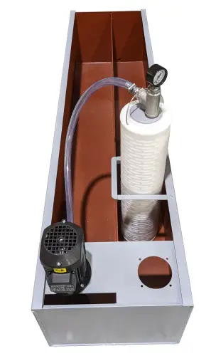
9.3.1.1.FILTRAmaq UNO
Self-contained equipment for the filtration of grinding/sharpening liquids, up to 2 µm. It is ready to be installed inside the tank of ELITE machines.
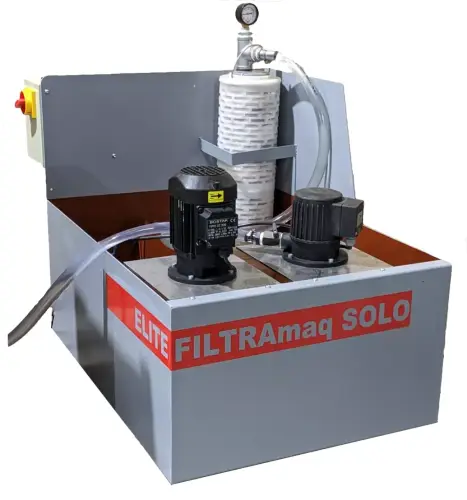
9.3.1.2.FILTRAmaq SOLO
Independent filtering system for one machine.
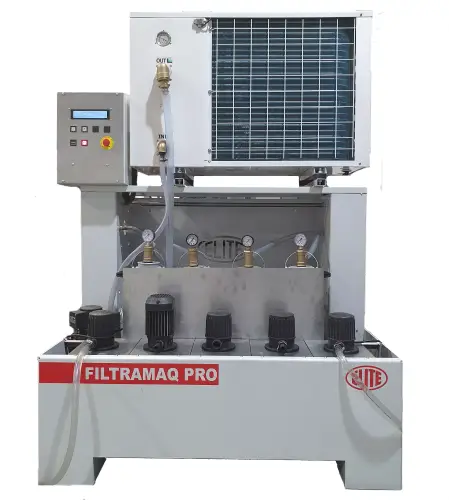
9.3.1.2.FILTRAmaq PRO
Centralized filtration system for the connection of up to 5 machines.
10. WARRANTY
All our machines are tested before being shipped. However, there can always be defects that are not observable with the naked eye.
Our machines are guaranteed against manufacturing or material defects under normal use and maintenance conditions.
The period of this guarantee is 12 months from the date of purchase and consists of the replacement of defective material.
The guarantee will be automatically canceled in the event of a modification outside our company. Or in manifest cases of misuse of the machine.
The guarantee does not include parts subject to normal wear due to use such as skids, lubrication cartridge, abrasives, etc.
12.DOWNLOAD MANUAL
13.FAQ
Question nr1
Answer no. 1