1. FIRST STEPS
Congratulations on your purchase of the ELITE model TR 3 AUTO setting machine.
Read this guide before you start.
The ELITE model TR 3 AUTO is an economical and low-maintenance automatic setting machine for band saws with a width of 10 to 80 mm.
You can view the product catalog at the following link: ELITE model TR 3 AUTO
This manual introduces you to the main functions of the setter in order to avoid risks to your health or that may cause a breakdown or premature wear of the machine.
In case of any doubt, please contact us directly or one of our authorized distributors.
Informative Note: The use described in the manual of this setter may present some variations in use since our machinery is subject to possible constructive modifications, depending on the incorporation of technological advances in our sharpening equipment.
2. SECURITY
2.1.Safety rules
Carefully observe and apply the following safety rules, non-observance of these rules may cause personal injury or damage to the machine itself.
The installation and maintenance of the machine described in this manual must be carried out only by operators who are familiar with its operation and have sufficient technical knowledge.
The ELITE model TR 3 AUTO setting machine has been designed for setting band saws with a width of 10 to 80 mm. excluding any other type of operation.
DANGER HIGH VOLTAGE

DANGER OF ACCIDENT

DANGER DUE TO SPARK PROJECTION

WEAR PROTECTIVE SHOES

DANGER FROM SHARP TOOLS

USE HEARING PROTECTORS
These warnings do not include all possible risks that could be caused by improper use of the machine. Therefore, the operator must proceed with prudence and observing the rules.
2.2.Use and preservation of the instruction manual
This instruction manual must be read and understood by all personnel who come into contact with the machine.
This guide is for:
- Indicate the correct use of the machine according to the type of work to be carried out.
- Provide the necessary instructions for the transport, adjustment and maintenance of the machine.
- Facilitate the order of spare parts and risk information.
Limits of use of the manual:
The machine is intended for professional use and therefore the experience of the operator is necessary and of vital importance.
Importance and conservation of the manual:
This manual must be considered an integral part of the machine and must therefore remain with it until the end of its use.
Additional information and clarifications:
The user, owner or maintenance person can contact the manufacturer to request any additional information on the use of the machine and the possible modalities of maintenance and repair intervention.
Expiration of responsibility:
The manufacturer is considered exempt from any responsibility in case of:
- Improper use of the machine
- Use of the machine by untrained persons
- Serious failures in scheduled maintenance
- Unauthorized interventions or modifications
- Use of non-original spare parts.
2.3.Declaration of conformity
The company hereby:
Elite Machines, SLU
Joan Oró, 27
ES-08635 Sant Esteve Sesrovires
Declares that the product indicated below, based on its conception and construction, as well as the version put on the market by our company, complies with the mandatory basic health and safety requirements of the CE directive.
This declaration loses its validity in the event of unauthorized modifications to the product.
Product name: ELITE TR 3 AUTO
Product type: Band saw setting machine
Serial number.: __
EC Directive Competences:
- EC Machinery Directive (2006/42/EC)
- European directive on electromagnetic compatibility (2014/30/EU)
- The protection purposes of the CE low voltage directive (2006/95/CE) were fulfilled according to annex I, nr. 1.5.1 of the machinery directive 2006/42/EC
The technical documentation was compiled by legal representative of the documentation:
Sergi Valls Gramunt
Joan Oró, 27
ES-08635 Sant Esteve Sesrovires
Date / manufacturer - Signature: __
Signatory data: Sergi Valls Gramunt, manager
3.TECHNICAL DATA
In the following table of information, find the list of technical specifications of the setter described in this manual.
| TECHNICAL DATA | ELITE TR 3 AUTO |
|---|---|
| Band saw width | From 10 to 80mm. (0.39" to 3,14") |
| Band saw thickness | From 0.5 to 1.2mm. (0.02" to 0.047") |
| tooth pitch | From 5 to 35mm. (0.19" to 1.37") |
| Machine size | 650 x 600 x 2600 mm. |
| Net weight | 50 kg |
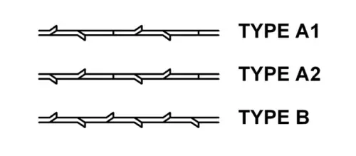
Types of setting
4. TRANSPORTATION
The TR 3 AUTO setting machine is delivered packed in a wooden box.
During all transport and transfer, the machine must be kept in its original vertical position, any variation in this position may lead to the loss of the guarantee.
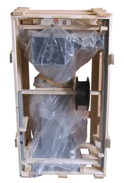
| Model | Packing dimensions | Gross Weight |
|---|---|---|
| TR 3 AUTO | 920 x 820 x 1560 mm. | 92 kg |
4.1.Unpacking and assembly instructions
Take special care when lifting the load: The load may not be centered!
To lift or move the load, use a forklift with blades long enough to support the machine, taking into account the width and depth of the machine when calculating the weights to be lifted.
To unpack, remove the front panel and the wooden blocking pieces or the fixing screws on the feet of the machine.
Once the machine has been transferred to its final work destination, you must fix the machine to the ground using the 4 screws placed on the base support of the machine. If this is not done, there is a high risk of the machine tipping over and causing serious injury to personnel and the machine itself.
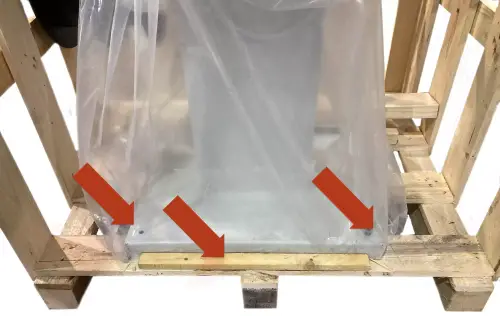
Once the machine is in its final location, you can also remove the protective film and other protections from the components, which secure and prevent the machine from moving.
Insert the rod with the rollers in their vertical position at the rear of the machine. Move the rollers so they can hold the blade ring in place during adjustment and sharpening operations. Lock the lower end of the support with the screws that you can find in the casing.
5.INSTALLATION
5.1.Machine placement
Before any work, make sure that the machine is well aligned and does not oscillate at any of its ends, in which case it must be shod to prevent movement. For its correct leveling it is necessary to use a leveling tool. This control must be carried out both longitudinally and transversally.
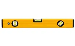
A poor leveling of the machine can cause unwanted vibrations and premature wear of the linear guides.
ATTENTION: The machine must not be used under any circumstances by unqualified or unauthorized personnel.
5.2.Electrical connection
Remember: Before connecting the machine, remove any guards the machine may have to protect components during transport.
DANGER HIGH VOLTAGE!
The TR 3 AUTO setting machine must be strictly connected to the voltage indicated in the machine order and on the machine itself. The connection to a voltage other than that indicated may cause a breakdown in the machine and represents a risk for people who use the machine.
For its connection to the electrical network, the machine requires only two phases and the ground connection.
This installation must be carried out by qualified technical personnel and checked with a voltage meter before turning on the machine.
It is absolutely essential that the cross-section of the connection cable is as required, that the machine has a dedicated socket protected against overloads and that it is as close as possible to the mains socket.
In case of an inadequate cable section, not enough current will reach the machine at the time of setting, causing a faulty and extremely brittle setting. This is one of the most important points since a very large number of possible setting problems are due to this problem.
We reject any responsibility for a wrong connection.
Once the connection has been made and checked, turn the main ON/OFF switch to the ON position.
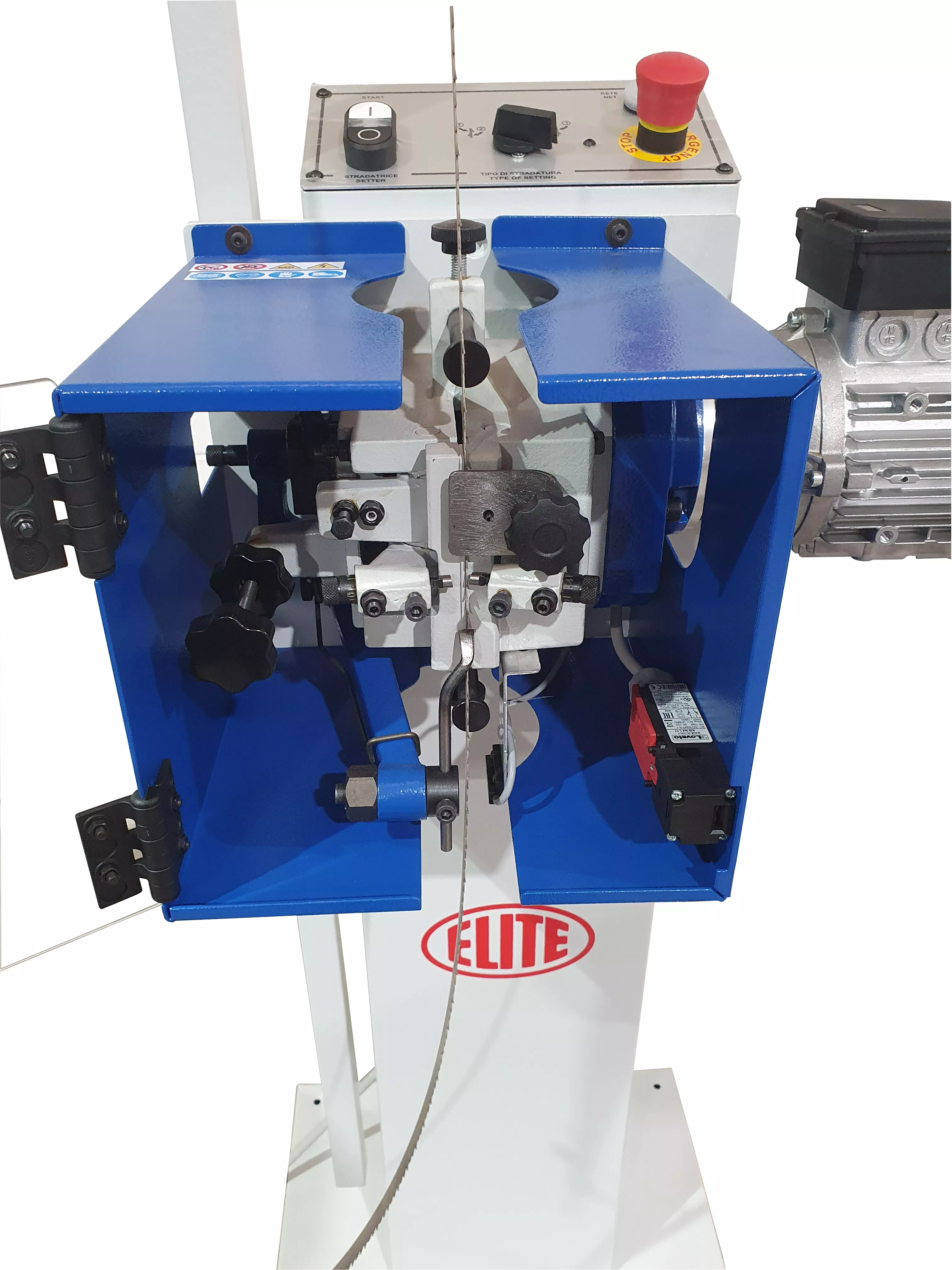
5.3.Main components of the machine
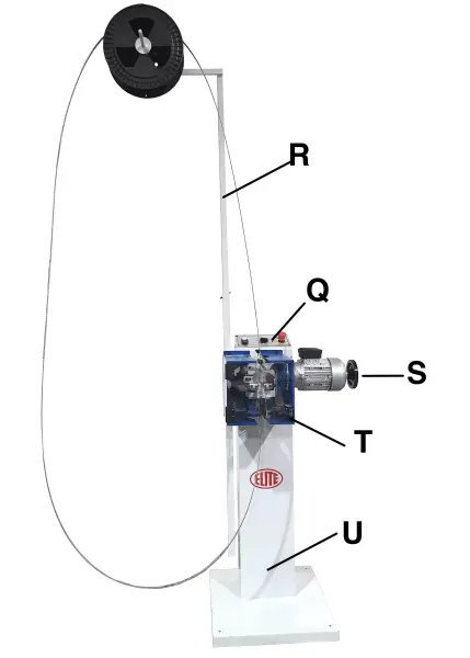
R. Rod of roll for bandsaw positioning
Q. Control panel
S. Motor and reducer unit of the setting machine
T. Setter unit
U.Base
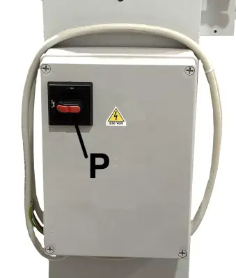
P. Main switch
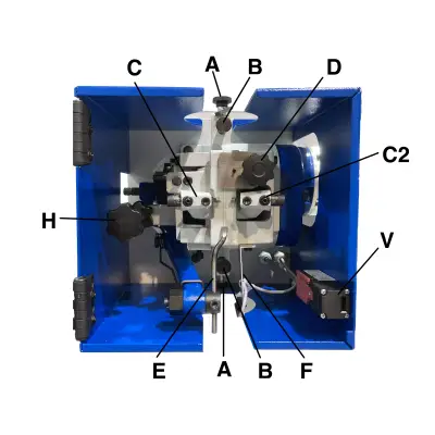
A. Blocking knobs of the band height regulators
B. Band height regulators
C1. Right lever (it supports the right hammer)
C2. Left lever (it supports the left hammer)
D. Knob of the device that presses the band
E. Tooth pusher
F. Sensor
H. Pitch regulator knob
V. Movable protective cover with sensor
Hammer (detail)
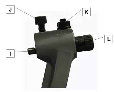
I. Litter hammer head
J. Little hammer blocking screw
K. Ring nut blocking screw
L. Ring nut for regulating the little hammer length
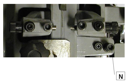
Clamp and arm of the tooth pusher (detail)
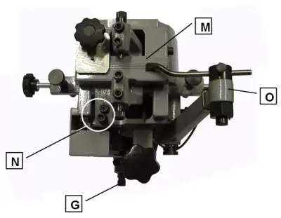
M. Vice
N. Vise regulation screw
O. Arm of the tooth pusher
G. Type of setting selector
6. START UP
In this section we show you how to operate the TR 3 AUTO to make it work.
NOTE: The data that appears in the different images are by way of example, each type of tool has its recommended data and an expert operator should know them.
DANGER: never manipulate the buttons on the control panel while performing maintenance on the machine: danger of very serious injury. It is strongly recommended to switch off and disconnect the machine from the mains when working inside it.
6.1. Power on the machine
The TR 3 AUTO setting machine has been designed for setting band saws with the maximum dimensions described above in the technical characteristics.
The machine is built from welded and machined parts.
6.1.1.Power on
After ignition, a warning light on the control panel lights up. This lamp indicates that the setting process can be started
6.1.2.Electrical connection
The TR 3 AUTO must be strictly connected to the voltage indicated in the machine order and on the machine itself. The connection to a voltage other than that indicated may cause a breakdown in the machine and represents a risk for people who use the machine.
This installation must be carried out by qualified technical personnel and checked with a voltage meter before turning on the machine.
It is absolutely essential that the cross-section of the connection cable is as required, that the machine has a dedicated outlet and is protected against overloads and shunts, and that it is as close as possible to the electrical outlet.
We reject any responsibility for a wrong connection.
Once the connection has been made and checked, turn the main ON/OFF switch to the ON position.
Elite Sharpening Machines, rejects all responsibility for a wrong connection, which in addition to causing a malfunction of the machine can harm people, animals or objects.
7. OPERATION OF THE WORK

7.1.Setting
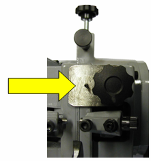
Before starting any other operation, you must rotate the hand wheel S till both little hammers C reach the off position. Thanks to this operation you can obtain the maximum opening of the vice M (see main components description in section 5.3)
Little hammer in off position (maximum opening)
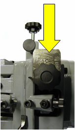
Lift the device that presses the band D and rotate it clockwise.
Closed:
Open:
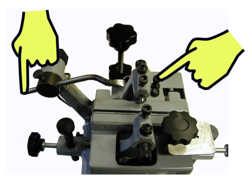
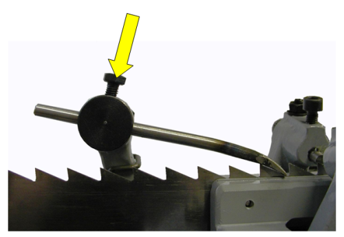
Press the screw N in order to open the vice M and lift the tooth pusher E in order to insert the band.
Insert the bandsaw in vice M, so that regulating the special supports B the bandsaw protrudes from the clamps at about halfway from the tooth. To regulate the supports, loosen knobs A and move pivots B to the right height. Then close the knob A.
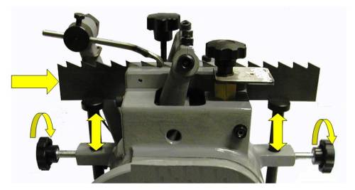
Using the screws N regulate the vice closure. The clamp closure must not hamper the band sliding.
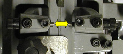
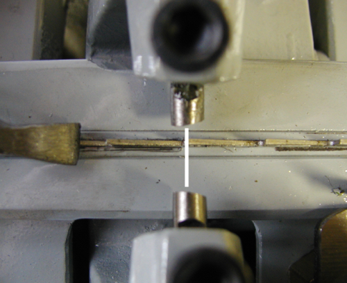
Regulate the pitch of the tooth using the special knob H. Each rotation of the handwheel S must correspond to the shifting of only one tooth of the band. If necessary, you can regulate the tooth pusher loosening blocking screws (see the following figure) and making it slide backwards and forwards in its housing.
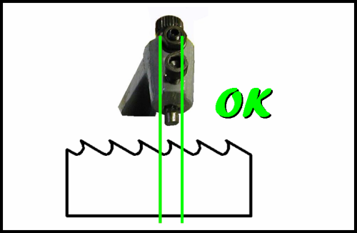
ATTENTION: The tip of the band tooth must be exactly in the middle between the two little clamps (see the following figure).
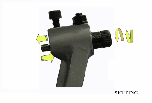
Regulate the quantity of the setting by the special graduated knobs L. If necessary, loosen screws J. By means of these knobs, the little hammer I moves backwards and forwards towards the tooth of the band. At the end of regulation, block clamps I by means of screws J.
Position again the device that presses the band D. Close door V and start the machine up by pressing 1 on the control panel Q.
The automatic stop at the end of a cycle is obtained through the application of small magnet (supplied together with the machine) on the edge of the already sharpened band. The magnet will produce the stop in the proximity of sensor F.
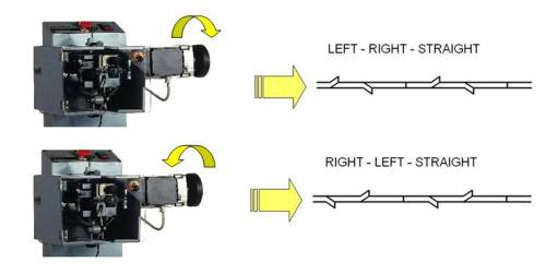
The machine has two ways of setting.
| TYPE | TEETH ARRANGEMENT | DIRECTION OF ROTATION OF HANDWHEEL | BEARING POSITION |
|---|---|---|---|
| A-1 | LEFT - RIGHT - STRAIGHT | CLOCKWISE | ON 3 LOBES CAM |
| A-2 | RIGHT - LEFT - STRAIGHT | ANTICLOCKWISE | ON 3 LOBES CAM |
| B | LEFT - RIGHT | BOTH | ON 2 LOBES CAM |
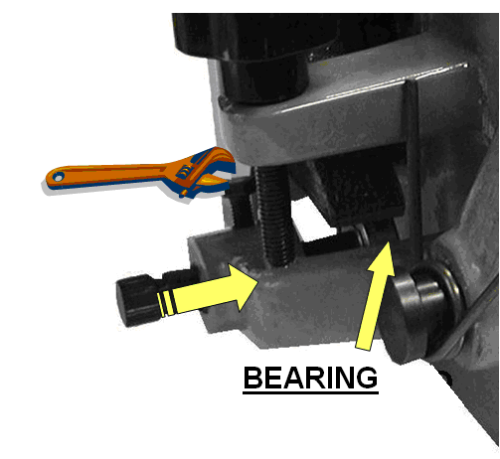
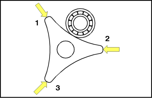
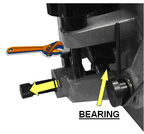
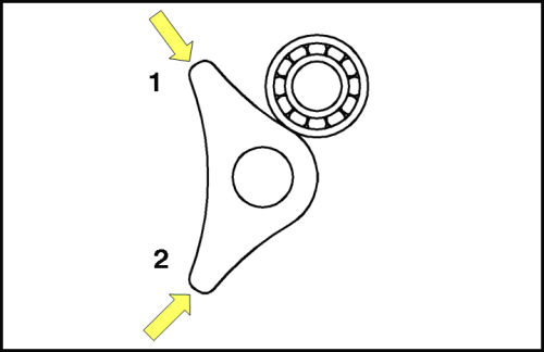
To pass from type of setting A to type of setting B, use selector G. Loosen the screw which blocks the pivot G and move the bearing on the part of the three lobes of the cam for setting type A, or on the part of the two lobes of the cam for setting type B.
TYPE A
With regard to setting type A:
A-1 = rotate motor S clockwise;
A-2 = rotate motor S anticlockwise;
TYPE B
For type B the both directions of rotation produce the same result.
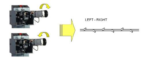
Setting machines are supplied already preset for type of setting A. The motor connected as above described, produces an anticlockwise rotation on the bandsaw machine. If you wish to obtain a clockwise rotation invert the connection. It is possible to obtain both settings A1 and A2 by connecting a phase converter to the machine.
WARNING!! When inserting a previously processed blade make sure to follow the already existing setting.
If for example during the previous processing one tooth had been bent rightwards operate in such a way that the hammer respects the previous bending direction.
7.2.Working technical characteristic
| WIDTH OF BAND SAW BLADE | Max. 80 mm |
| PITCH | Max. 35mm |
Types of setting
7.3. Problems and solutions
If problems appear, read this section. Problems can be solved using other different parameters.
1. The machine does not start.
Solution: Check if the machine is correctly connected to the correct phase electrical network. Check if the electrical voltage (voltage) corresponds to that indicated on the machine. Check if the motors rotate in the direction indicated by the arrows; if not, reverse the position of the two wires in the power plug.
2. For setting a band that has already been set, the new setting operation must be like the previous one, otherwise teeth may break
Solution: Choose the type of setting. It must be like the one already present on the band. The action of hammers must respect the previous bending direction.
3. Regulate the closure of the vice. A wrong closure of the vice may cause the breakage of the vice itself or of the tooth pusher.
Solution: Before opening the vice for inserting the band, make sure that the little hammers are completetly open. Pay attention when you regulate the closure of the vice by means of the screw N. You must nos clasp too much in order not to hamper the band sliding.
**4. Not all the bands require the same vice regulation: it depends on their thickness. If you do not use the right closure, the vice may break.
Solution: Regulate again the closure of the vice using the screw N whenever you change the type of band.
**5. When you use very worn bands, the tooth pusher E may not work correctly
Solution: There is no solution, because a too worn band cannot be set any more.
**6. For a good setting, it is necessary and very important to regulate the little hammers. A wrong regulation may lead to unwanted results.
Solution: Before setting the whole band, do a regulation test of the little hammers
**7. The machine stops inexplicably.
Solution1: It may be due to the magnet used for the automatic stop of sharpening operation. Check its position and, if necessary, position it correctly.
Solution2: The protective cover V may be open or closed wrongly.
7.4. Technical assistance service
At ELITE we try to satisfy our customers through reliable and easy-to-use products. However, if you experience any incident while using the machine, do not hesitate to contact us as soon as possible directly or through our authorized distributors, who will assist you, if available in your country, with better proximity and professionalism.
We wish you to enjoy this product for many years, please: when the useful life of the setter ends, dispose of it correctly to the necessary organisms for its correct disposal and recycling.
8. MAINTENANCE
8.1.Preventive maintenance
The TR3 AUTO does not require any particular maintenance, thanks to its improved concept. However, a good cleaning done periodically is required. All maintenance, repair or cleaning operations must be carried out with the machine turned off. Use compressed air or a rag.
Over time, the hammers (I) as well as the vise plates (M) can wear out and will then need to be replaced. Please contact us if you need any replacement parts.
Use the equipment only in dry environments. The temperature must be between 5 and 40ºC. A relative humidity greater than 90%, as well as a saline environment, would cause premature corrosion of the machine.
8.2. Exploded view
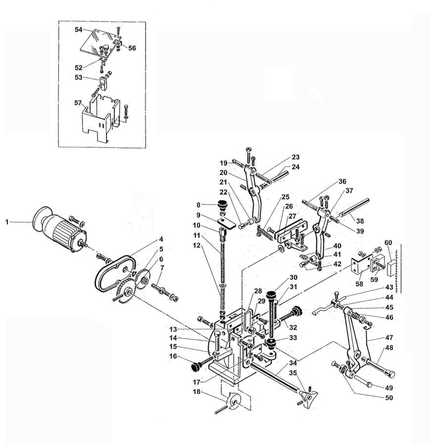
Part List
PART. N. 1 Motor
PART. N. 4 Cover
PART. N. 5 Motor gear
PART. N. 6 Bandsaw machine gear
PART. N. 7 Short pivot
PART. N. 8 Knob
PART. N. 9 Device for pressing the band
PART. N. 10 Bush of device for pressing the band
PART. N. 11 Pivot diameter 10
PART. N. 12 Spring
PART. N. 13 Plate for vice
PART. N. 14 Pivot for regulating the height of the band
PART. N. 15 Body
PART. N. 16 Knob for blocking the pivot that regulates the height of the band
PART. N. 17 Plate
PART. N. 18 Inner cam
PART. N. 19 Screw for regulating the length of little hammers
PART. N. 20 Right lever
PART. N. 21 Roll
PART. N. 22 Pivot of roll
PART. N. 23 Little hammer (right)
PART. N. 24 Pivot of lever
PART. N. 25 Spring
PART. N. 26 Plate for clamp
PART. N. 27 Vice
PART. N. 28 Little gib
PART. N. 29 Small roll
PART. N. 30 Knob for pitch regulation
PART. N. 31 Pivot for regulating the height of the band
PART. N. 32 Knob for blocking the pivot that regulates the height of the band
PART. N. 33 Blocking knob
PART. N. 34 Shaft
PART. N. 35 External cam
PART. N. 36 Little hammer (left)
PART. N. 37 Left lever
PART. N. 38 Pivot of lever
PART. N. 39 Screw for regulating the length of little hammers
PART. N. 40 Spring
PART. N. 41 Roll
PART. N. 42 Pivot of roll
PART. N. 43 Tooth pusher
PART. N. 44 Pivot of tooth pusher holder
PART. N. 45 Arm of tooth pusher
PART. N. 46 Spring
PART. N. 47 Spring
PART. N. 48 Pivot of arm
PART. N. 49 Pivot of bearing
PART. N. 50 Bearing
PART. N. 52 Sensor key
PART. N. 53 Door sensor
PART. N. 54 Door
PART. N. 56 Hinge
PART. N. 57 Cover
9.ACCESSORIES AND CONSUMABLES
10.WARRANTY
All our machines are tested before being shipped. However, there can always be defects that are not observable at first sight.
Our machines are guaranteed against manufacturing or material defects under normal use and maintenance conditions.
The period of this guarantee is 12 months from the date of purchase and consists of the replacement of defective material.
The guarantee will be automatically canceled in the event of a modification outside our company. Or in manifest cases of misuse of the machine.
The guarantee does not include parts subject to normal wear due to use such as skids, lubrication cartridge, abrasives, etc.
11.DOWNLOAD MANUAL
12.FAQ
Question nr1
Answer no. 1